
Audio microphone detection using auto-tracking current comparator

a technology of auto-tracking current comparator and audio microphone, which is applied in the direction of transducer details, instruments, different amplifiers, etc., can solve the problem of not being able to determine the load current provided to the microphone, and achieve the effect of saving chip area, cost-effective microphone detection, and accurate determination of load curren

Active Publication Date: 2022-03-22
NUVOTON
View PDF10 Cites 0 Cited by
  • Summary
  • Abstract
  • Description
  • Claims
  • Application Information

AI Technical Summary

Benefits of technology

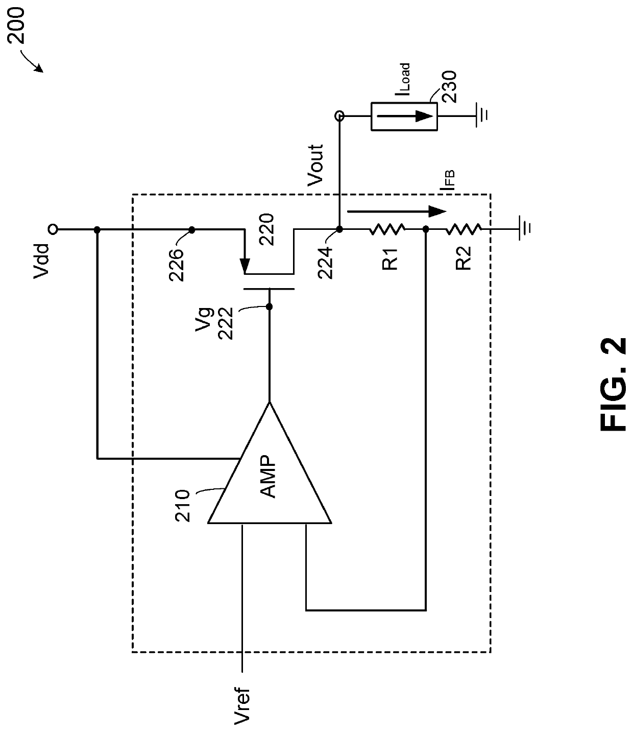
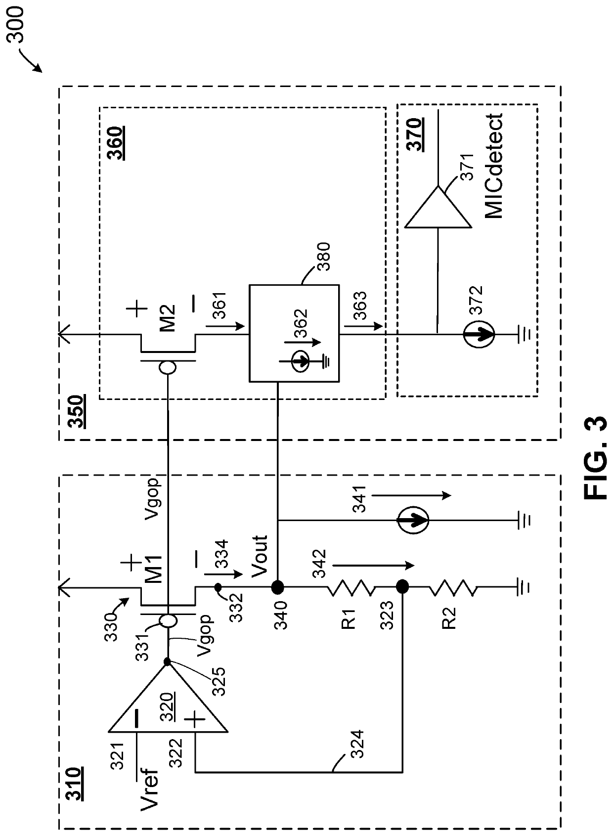
The present invention provides methods and apparatus with a current tracking system to accurately monitor the load current on the microphone power supply pin and reproduce the same voltage as the output transistor in the voltage regulator. This allows for more accurate determination of the load current, without the need for an extra microphone detection pin and reducing chip area and cost. Additionally, low-offset voltage comparators are not required, further reducing costs.

Problems solved by technology

Some conventional circuits require an extra pin and complicated voltage comparators for this determination.
Other conventional circuits use a current comparator, but cannot determine the load current provided to the microphone to determine the type of microphone connected to the system.

Method used


Image

  • Audio microphone detection using auto-tracking current comparator
  • Audio microphone detection using auto-tracking current comparator
  • Audio microphone detection using auto-tracking current comparator

Examples


Embodiment Construction

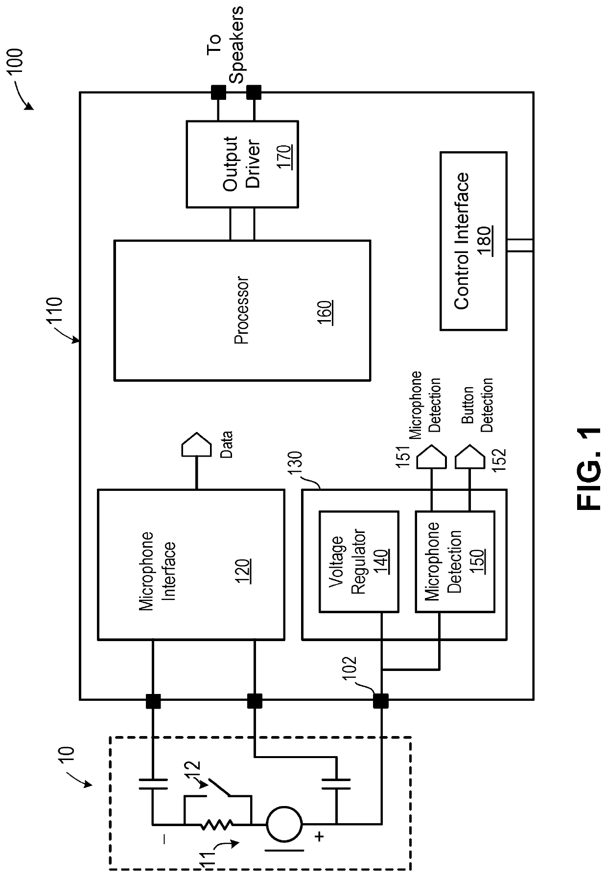
[0024]FIG. 1 is a simplified block diagram illustrating an audio system according to some embodiments of the present invention. Referring to FIG. 1, the audio system 100 includes an external microphone module 10 and an integrated circuit 110 for receiving audio signals from microphone module 10 and providing output signals to speakers (not shown). Microphone module 10 can include a microphone 11 and a button 12. Microphone 11 can be any suitable microphone and button 12 can be used for turning the microphone on and off. Integrated circuit 110 can include a microphone interface circuit 120, a power supply module 130, and a microphone detection circuit 150. Integrated circuit 110 can also include a processor 160, an output driver 170, and a control interface circuit 180.

[0025]Microphone interface circuit 120 is coupled to microphone module 10 to receive audio input signals and provide audio data to processor 160, which provides processed signals to output driver 170 for driving speake...


PUM


Abstract

An integrated circuit includes a current detection circuit configured for coupling to an output terminal of a voltage regulator, the output terminal providing a total current that is divided into a load current to a load device and a feedback current for providing a feedback signal to the voltage regulator. The current detection circuit includes a current sampling circuit and a current comparator circuit. The current sampling circuit provides a first current that is proportional to the total current, a second current that is proportional to the feedback current, and a third current that is proportional to the load current. The current comparator circuit is configured to compare the third current with a threshold current, and output a detection signal that indicates whether the third current matches the threshold current, thereby indicating a target load device is detected.

Description

BACKGROUND OF THE INVENTION[0001]This invention relates to electronic circuits. In particular, embodiments of the invention are directed to load device detection circuits for a voltage regulator. Some embodiments described herein are applied to a microphone detection circuit for an audio system. However, the circuit and methods described here can be used in applications which involve the accurate determination of a load current for a voltage regulator.[0002]In an audio system, an integrated circuit is often used to receive audio signals from a microphone and provide output signals to drive speakers. It is desirable for the integrated circuit to be able to function with different microphones, which may have different voltage and current characteristics. Therefore, such an integrated circuit often includes a microphone detection circuit to detect when a microphone is connected to the system and determine what kind of microphone is connected to the system.[0003]Conventional solutions t...

Claims


Application Information

Patent Timeline
Patent Type & Authority Patents(United States)
IPC IPC(8): G05F1/56G05F1/575G05F1/59G05F1/595H04R3/00H04R29/00
CPCG05F1/575H04R3/00H04R29/004G01R19/0092H04R31/006G05F1/56H03F3/45H04R2420/05
Inventor WU, CHANG-XIANSANDHU, BAL S.
Owner NUVOTON
Learn More