
Gas turbine engine having optimized fan

a technology of gas turbine engine and fan blade, which is applied in the direction of blade accessories, machines/engines, blade manufacture, etc., can solve the problems of compromising other aspects of engine design, affecting the performance of the engine, so as to achieve the effect of low weight, less susceptible to deformation and/or damage, and less deformation or damage to the fan blad

Active Publication Date: 2022-03-08
ROLLS ROYCE PLC
View PDF13 Cites 0 Cited by
  • Summary
  • Abstract
  • Description
  • Claims
  • Application Information

AI Technical Summary

Benefits of technology

The gas turbine engines described in this patent have the advantage of being strong against foreign objects, such as bird strikes, while also being lightweight. The design of the fan blades allows for better optimal aerodynamic design, while carbon fibre fan blades can be used without compromising weight and efficiency. The fan is directly coupled to at least one turbine stage, which eliminates the need for a gearbox between them. The fan blades may also have a leading edge sheath with improved impact resistance. Overall, the engines are designed to achieve greater impact tolerance, reduced complexity, and improved performance.

Problems solved by technology

Such bird strikes may occur when the engine ingests one or more birds during operation.
The requirement to be able to withstand bird strikes typically compromises other aspect of the engine design.
By way of further example, the design and materials of the fan system (for example the fan blades and / or fan containment case) may be more complex and expensive than would otherwise be required in the absence of the requirement to be able to withstand bird strikes.
Such carbon fibre fan blades may be particularly susceptible to impact damage.
Accordingly, the design of carbon fibre fan blades may typically be compromised—for example in terms of weight and / or aerodynamic efficiency—by the requirement to be able to adequately contend with strikes from foreign objects.

Method used


Image

  • Gas turbine engine having optimized fan
  • Gas turbine engine having optimized fan
  • Gas turbine engine having optimized fan

Examples


Embodiment Construction

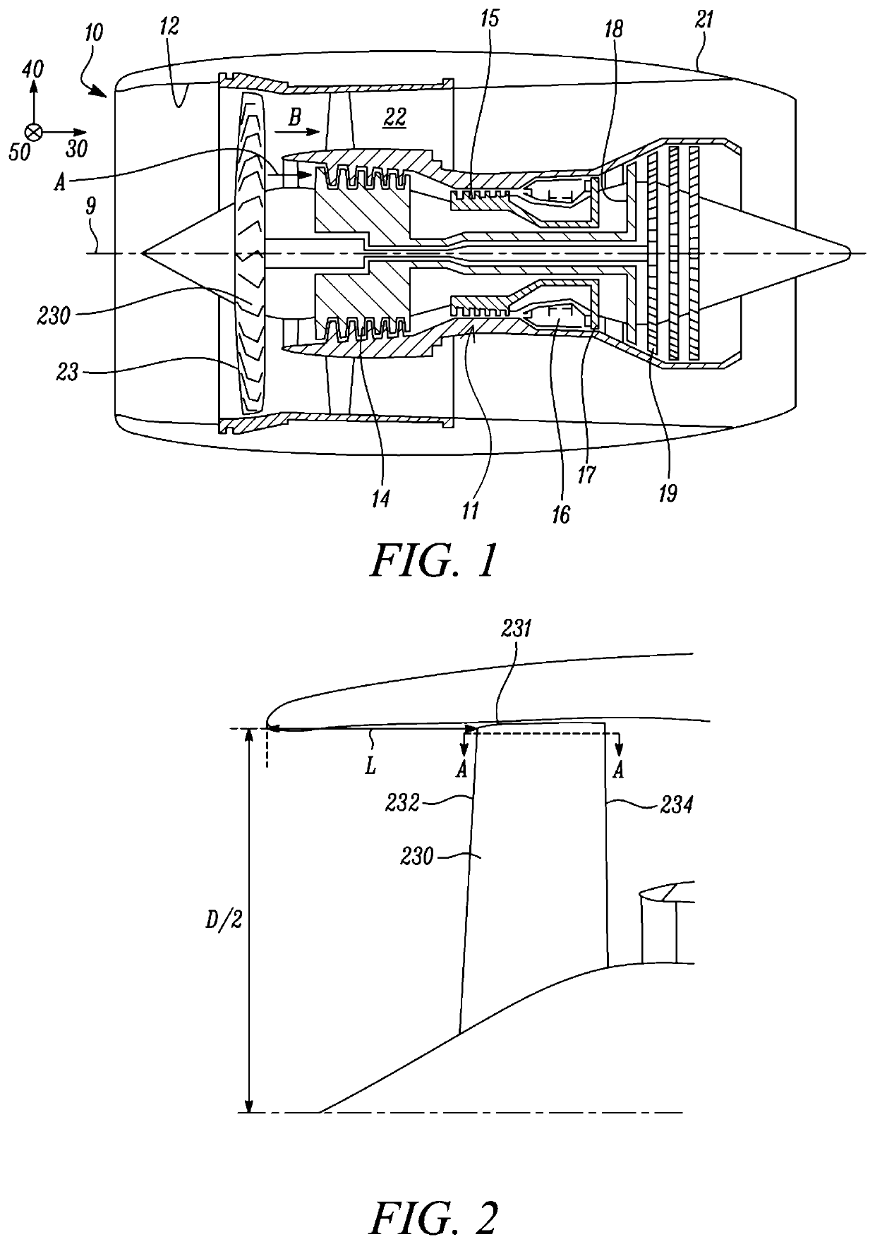
[0064]FIG. 1 illustrates a gas turbine engine 10 having a principal rotational axis 9. The engine 10 comprises an air intake 12 and a propulsive fan 23 that generates two airflows: a core airflow A and a bypass airflow B. The gas turbine engine 10 comprises a core 11 that receives the core airflow A. The engine core 11 comprises, in axial flow series, a low pressure compressor 14, a high-pressure compressor 15, combustion equipment 16, a high-pressure turbine 17, an intermediate-pressure turbine 18, and a low-pressure turbine 19. A nacelle 21 surrounds the gas turbine engine 10 and defines a bypass duct 22 and a bypass exhaust nozzle. The bypass airflow B flows through the bypass duct 22.

[0065]In use, the core airflow A is accelerated and compressed by the low pressure compressor 14 and directed into the high pressure compressor 15 where further compression takes place. The compressed air exhausted from the high pressure compressor 15 is directed into the combustion equipment 16 whe...


PUM


Abstract

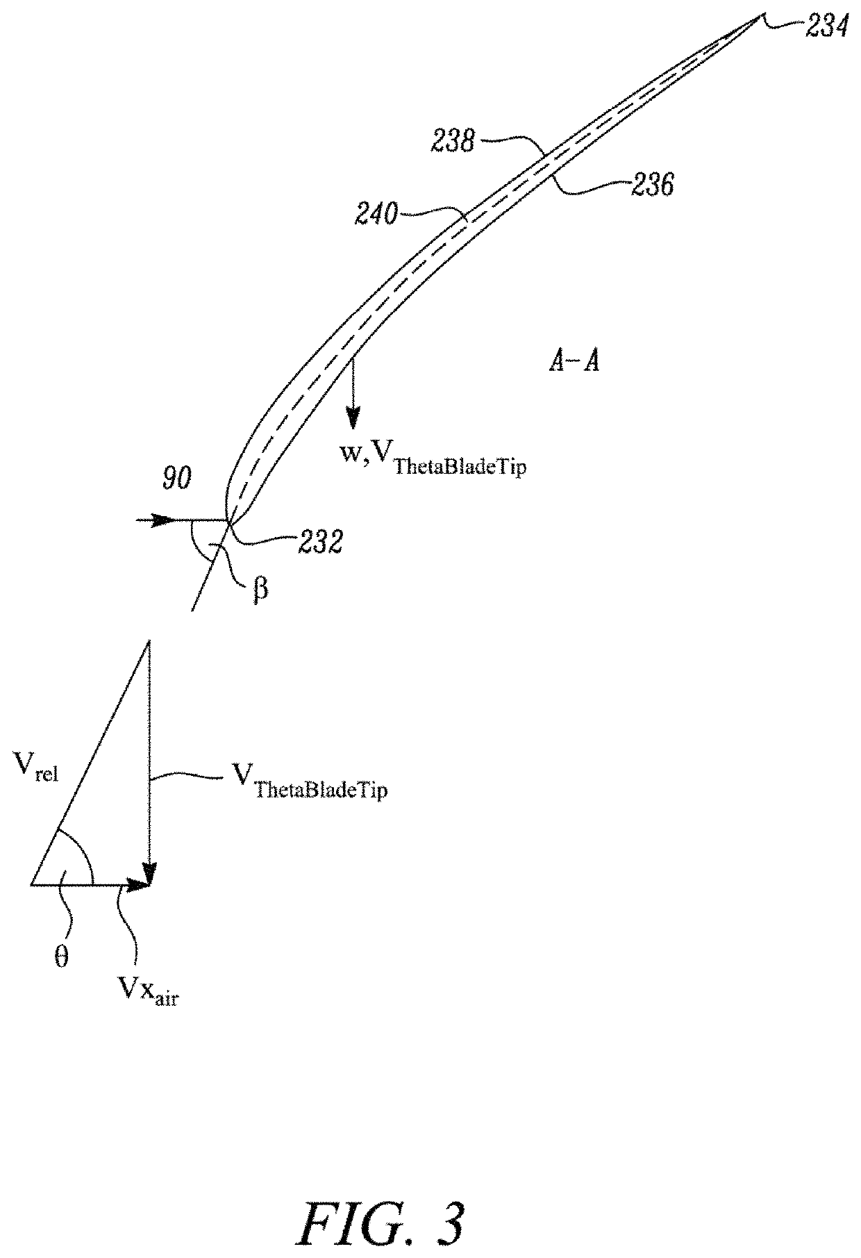
A gas turbine engine comprises carbon fibre fan blades. At cruise conditions, the fan tip air angle θ in the range: 64 degrees≤θ≤67 degrees. Additionally or alternatively, the fan blade tip angle β is in the range of from 62 to 69 degrees. Arrangements in accordance with the present disclosure provide advantages which may include improved bird-strike performance. This may allow advantages associated with carbon fibre fan blades to be better exploited.

Description

CROSS-REFERENCE TO RELATED APPLICATIONS[0001]This specification is based upon and claims the benefit of priority from UK Patent Application Number 1814315.6 filed on 4 Sep. 2018, the entire contents of which are incorporated herein by reference.BACKGROUND1. Field of the Disclosure[0002]The present disclosure relates to a gas turbine engine. Aspects of the present disclosure relate to a gas turbine engine having improved efficiency and / or capability to withstand bird strikes.2. Description of the Related Art[0003]The design of a modern gas turbine engine must balance a number of factors. Such factors include, for example, engine operability and / or stability during operation, engine efficiency (for example optimized efficiency over a typical flight cycle), engine size, and engine weight. A further consideration for a modern gas turbine engine is the capability to withstand bird strikes.[0004]Such bird strikes may occur when the engine ingests one or more birds during operation. Typica...

Claims


Application Information

Patent Timeline
Patent Type & Authority Patents(United States)
IPC IPC(8): F01D5/14F01D5/28
CPCF01D5/141F01D5/282F05D2240/307F05D2220/36F01D5/20F05D2250/711
Inventor BENSON, CHRISTOPHERBARALON, STEPHANE M M
Owner ROLLS ROYCE PLC
Learn More