
Metal pallet

a metal pallet and metal technology, applied in the field of industrial pallets, can solve the problems of more expensive manufacturing of metal pallets than wood pallets, wood (and plastic) pallets are considered fire hazards, metal pallets are more expensive than wood pallets, etc., to improve the deflection resistance in the assembly, increase the resistance to shear loads, and manufacture relatively inexpensively

Active Publication Date: 2022-02-08
RICKABAUGH MICHAEL G
View PDF51 Cites 2 Cited by
  • Summary
  • Abstract
  • Description
  • Claims
  • Application Information

AI Technical Summary

Benefits of technology

The patent text explains that pallet assemblies can be designed to resist shear loads, such as those caused by racking forces. By maintaining dissimilar outer and inner angles, the assembly can be manufactured from light-weight sheet metal and still meet industry specifications. The technical effect is improved deflection resistance and reduced manufacturing costs.

Problems solved by technology

Wood (and plastic) pallets are considered fire hazards.
Metal cannot harbor pathogens, invasive species of insects or plant diseases, is not considered a fire hazard, is typically not treated with hazardous chemicals.
Despite these advantages, metal pallets also have an array of inherent disadvantages.
Metal pallets are more expensive to manufacture compared to wood pallets.
However, the higher initial cost can be expected to invert to lower long-term cost due to longer service life of metal pallets compared to wood pallets.
Metal is slippery compared to wood.
However, moving to light gauge sheet metal typically results in a reduction ins load carrying capacity and / or decreased resistance to racking.
Unfortunately, a longer service life means more opportunities for exposure to damage.
Damage, caused overwhelmingly by fork truck usage, can cause unsafe stacking conditions.

Method used


Image

  • Metal pallet
  • Metal pallet
  • Metal pallet

Examples


Embodiment Construction

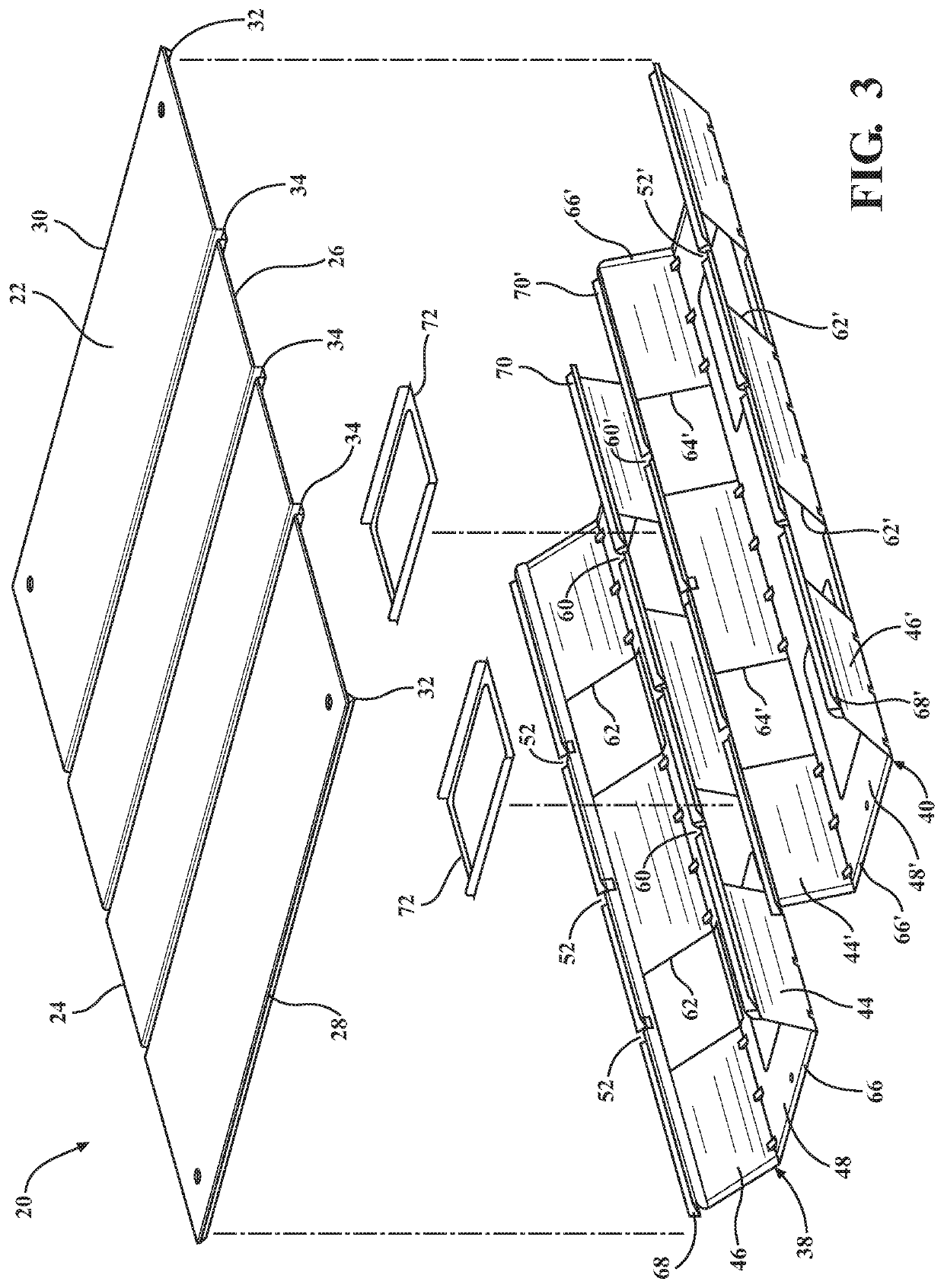
[0033]Referring to the figures, wherein like numerals indicate like or corresponding parts throughout the several views, a fabricated sheet metal pallet assembly is generally shown at 20 in FIGS. 1-12.

[0034]The assembly 20 includes a deck 22 upon which loads / cargo (not shown) are placed. The deck 22 has an upwardly facing top surface, and a downwardly facing bottom surface. The deck 22 can take any number of geometric shapes, but in the most common and traditional configuration has a generally rectangular in shape dimensioned to suit a particular intended application or general class of applications. As perhaps best shown in FIG. 1, the geometric shape of the deck 22 is defined, generally, by left 24 and right 26 longitudinal edges. In the illustrated examples, the left 24 and right 26 longitudinal edges are arranged parallel to one another. The deck 22 also has first 28 and second 30 transverse edges. The first 28 and second 30 transverse edges are also arranged parallel to one ano...


PUM


Abstract

A sheet metal pallet assembly includes a deck and an undercarriage. The deck is reinforced about its outer edges by longitudinal and transverse perimeter girding. The deck is further reinforced by one or more transverse reinforcement ribs and interior longitudinal girding. The undercarriage is composed of left and right fork tube risers joined together by bridges. The fork tube risers are configured to receive the tines of a forklift. Each fork tube riser has inner and a outer legs, each splayed at an a respective angle. Preferably, the splay angle of the outer leg is greater than the splay angle of the inner leg. The ends of each fork tube riser are folded over with a hem to improve strength and present a blunt edge. The undercarriage may, optionally, be fabricated from a single monolithic piece of sheet metal.

Description

CROSS REFERENCE TO RELATED APPLICATIONS[0001]This application claims priority to Provisional Patent Application U.S. 62 / 923,935 filed on Oct. 21, 2019, the entire disclosure of which is hereby incorporated by reference and relied upon.BACKGROUND OF THE INVENTIONField of the Invention[0002]The invention relates generally to industrial pallets, and more particularly to a pallet fabricated from sheet metal.Description of Related Art[0003]A pallet, or skid, is used in the storage and transport of goods to enable lifting by a forklift, pallet jack, or other type of handling device. Goods are typically secured to a pallet with a suitable strapping. In many cases, pallets are designed and intended to be re-used multiple times.[0004]While pallets are commonly made of wood, in some cases wood is known to present certain disadvantages. For example, laws may require pallets shipped across certain borders to be made of materials that are incapable of being a carrier of invasive species of insec...

Claims


Application Information

Patent Timeline
Patent Type & Authority Patents(United States)
IPC IPC(8): B65D19/08
CPCB65D19/08B65D2519/00024B65D2519/00059B65D2519/00407B65D2519/00796B65D19/0014B65D19/0024B65D19/0046B65D2519/00129B65D2519/00273B65D2519/00288B65D2519/00318B65D2519/00323B65D2519/00348B65D2519/00333B65D2519/00437B65D2519/00562B65D2519/00567
Inventor RICKABAUGH, MICHAEL
Owner RICKABAUGH MICHAEL G
Learn More