Eureka AIR delivers breakthrough ideas for toughest innovation challenges, trusted by R&D personnel around the world.

Sponge fixing mechanism for sponge mop

Active Publication Date: 2022-01-18
DCLEAN ENTERPRISE
View PDF14 Cites 0 Cited by
  • Summary
  • Abstract
  • Description
  • Claims
  • Application Information

AI Technical Summary

Benefits of technology

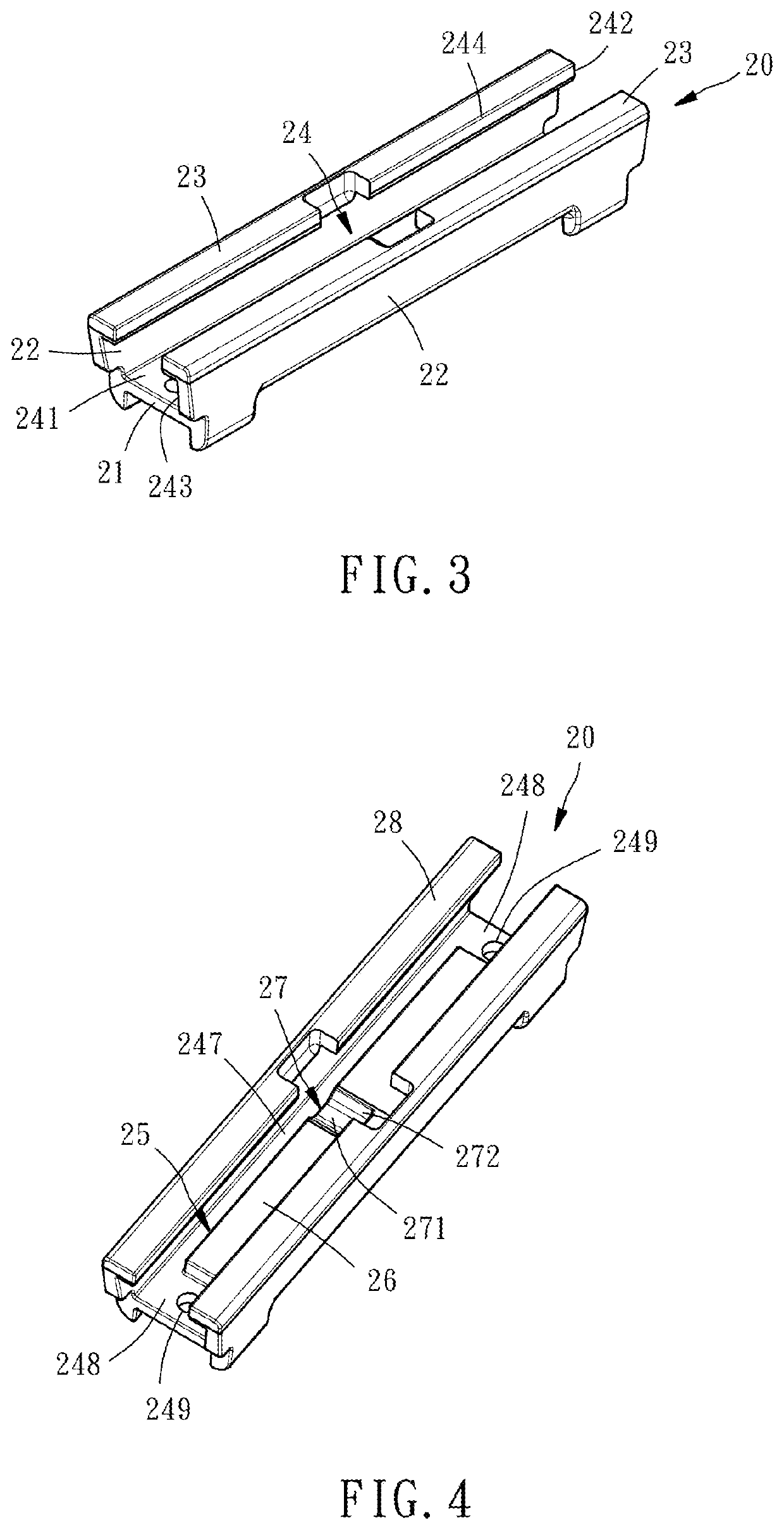
The present invention provides a sponge fixing mechanism for a sponge mop, which allows users to change the sponge more easily and conveniently. The mechanism includes a first fastener and a second fastener that can be separated from each other to remove the sponge. The first fastener has a chute with a latching recess and a latching protrusion that can be engaged and disengaged by sliding the second fastener. The second fastener has a stop portion and a rib that fit into a groove on the first fastener to ensure stable attachment. The mechanism also includes a cantilever and a slot for easy engagement and disengagement of the fasteners. The invention allows users to easily and conveniently replace the sponge without hindering the use of the mop.

Problems solved by technology

In this way, the process of dismounting the sponge not only requires the use of tools but will also be hindered by the holder block of the squeezer.
It may also make the process of dismounting the sponge more inconvenient due to the long handle and the space it takes.

Method used


Image

  • Sponge fixing mechanism for sponge mop
  • Sponge fixing mechanism for sponge mop
  • Sponge fixing mechanism for sponge mop

Examples


Embodiment Construction

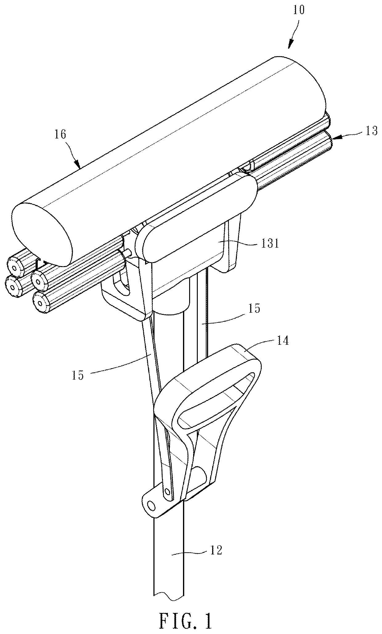
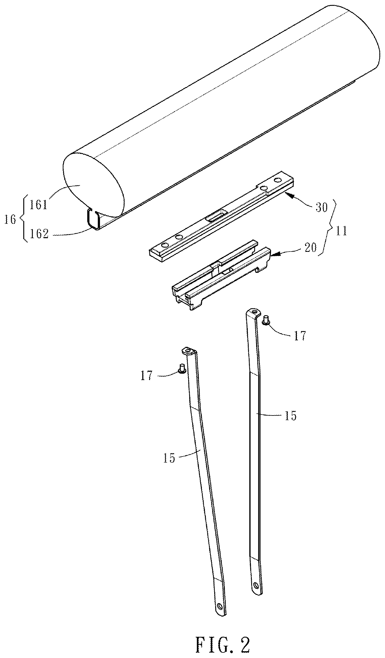
[0021]Referring to FIGS. 1 and 2, a sponge fixing mechanism 11 of a sponge mop 10 provided by a preferred embodiment of the present invention comprises a first fastener 20 as shown in FIGS. 3 and 4 and a second fastener 30 as shown in FIGS. 5 and 6. The material of the first fastener 20 and the second fastener 30 can be (but not limited to) plastic. The first fastener 20 is used to install in the main structure of the sponge mop 10. More specifically, the main structure of the sponge mop 10 described above comprises a handle 12 for holding by the user, a squeezer 13 provided at one end of the handle 12, a lever 14 pivoted on the handle 12 and two connecting rods 15 connected between the lever 14 and the first fastener 20. This part is similar to conventional sponge mops, and the applicant will not describe it in detail here. The second fastener 30 is used to hold a sponge unit 16 so that the sponge unit 16 is detachably fixed to the first fastener 20 through the second fastener 30, ...


PUM


Abstract

A sponge fixing mechanism for sponge mop includes a first fastener and a second fastener. The first fastener has a chute and a mating surface in the chute. The chute has an outlet and an inlet respectively located at two opposite ends of the first fastener. The second fastener has a mating surface and is installed in the chute and detachably fastened to the first fastener with the mating surface thereof in sliding contact with the mating surface of the first fastener. One of the first fastener and the second fastener has a latching recess recessed from the mating surface thereof. The first fastener and the second fastener are fastened together by elastically engaging the latching protrusion into the latching recess.

Description

BACKGROUND OF THE INVENTION1. Field of the Invention[0001]The present invention relates to sponge mops, and more particularly to a sponge fixing mechanism for sponge mop.2. Description of the Related Art[0002]Taiwan patent M276548 discloses a sponge mop, which mainly comprises a handle for the user to hold, a squeezer located at the bottom end of the handle, a lever pivotally connected to the handle, two connecting rods with the top ends thereof respectively pivoted to the lever and the bottom ends thereof extending into a holder block of the squeezer, a sponge connected to the bottom ends of the connecting rods by a chuck and a pivot seat. In detail, the chuck is fixedly clamped on the top of the sponge, and the pivot seat is pivotally connected to the bottom end of the two connecting rods. The chuck and the sponge are detachably fixed to the pivot seat by a plurality of bolts. Thereby, when the user pivot the lever upward, the chuck and the sponge are moved toward the inside of th...

Claims


Application Information

Patent Timeline
IPC IPC(8): A47L13/144A47L13/257A47L13/46
CPCA47L13/144A47L13/257A47L13/46A47L13/60
Inventor CHENG, CHAO-WEI
Owner DCLEAN ENTERPRISE
Why Eureka
Eureka Blog
Learn More