
Porous material, cell structure, and method of producing porous material

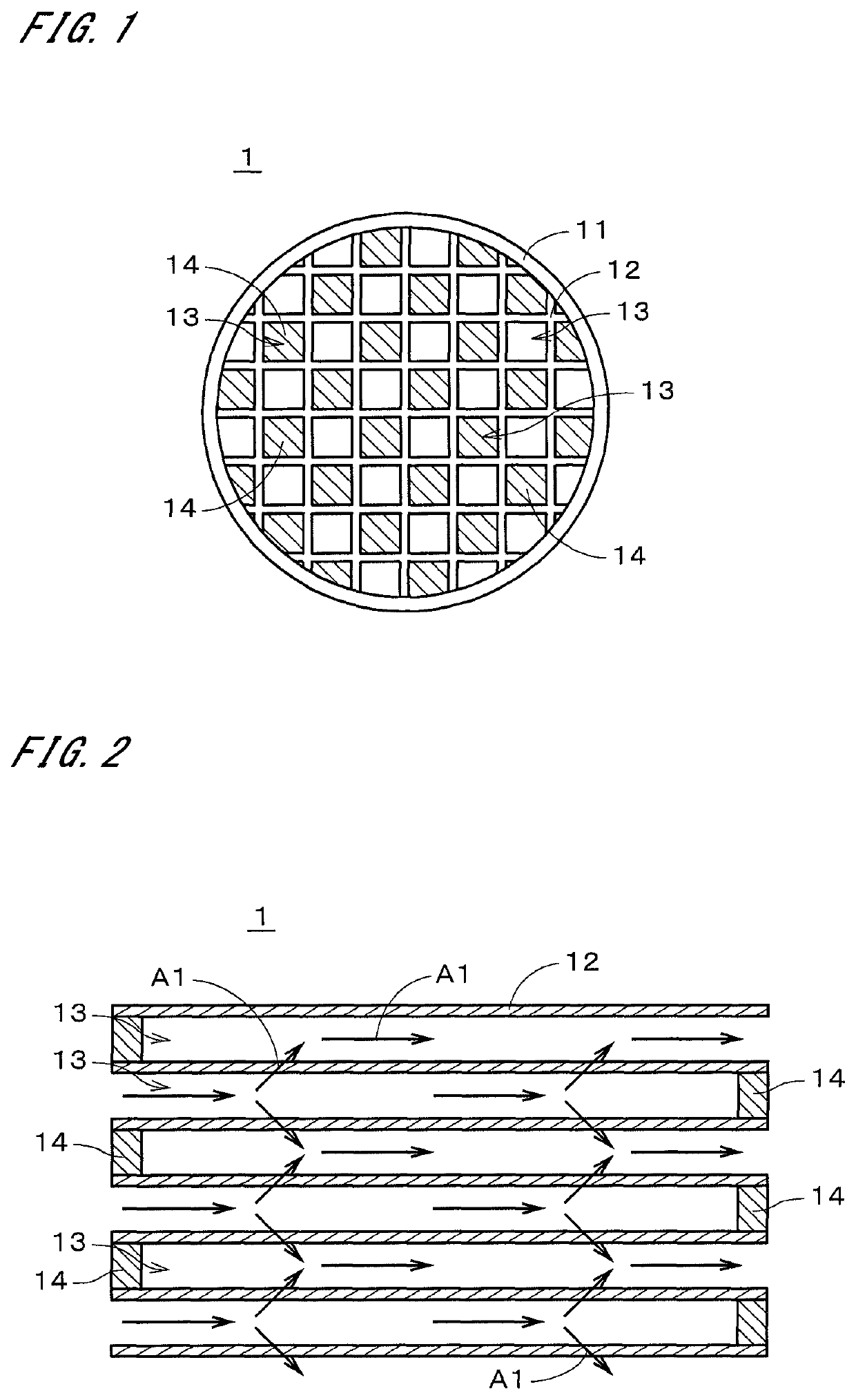
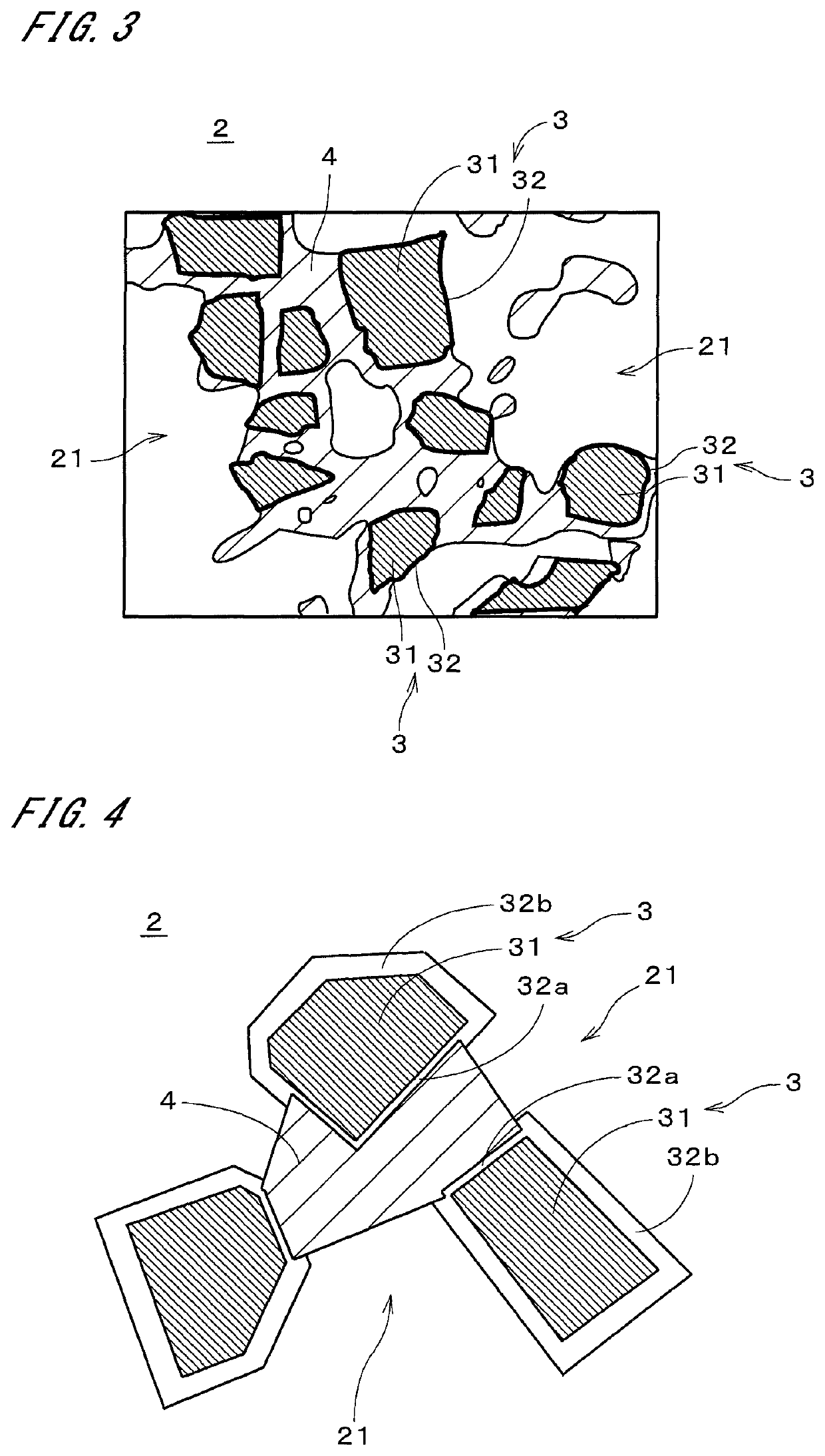
a cell structure and porous material technology, applied in the field of porous material, can solve problems such as complicated control, and achieve the effect of reducing the thermal expansion coefficient of porous material and improving oxidation resistan

Active Publication Date: 2022-01-04
NGK INSULATORS LTD
View PDF13 Cites 0 Cited by
  • Summary
  • Abstract
  • Description
  • Claims
  • Application Information

AI Technical Summary

Benefits of technology

The present invention is about a porous material with improved resistance to oxidation. The invention aims to reduce the thermal expansion coefficient of the material. The invention can achieve this target.

Problems solved by technology

At this time, the porous material with the oxide films formed therein has a high thermal expansion coefficient due to phase transition of the cristobalite, and therefore complicated control such as temperature condition control is necessary in order to appropriately support the catalyst.

Method used


Image

  • Porous material, cell structure, and method of producing porous material
  • Porous material, cell structure, and method of producing porous material
  • Porous material, cell structure, and method of producing porous material

Examples


examples

[0069]Next, examples will be described. Here, porous materials (honeycomb structures) were produced as Examples 1 to 5 and Comparative Examples 1 to 3 under conditions given by Table 1.

[0070]

TABLE 1Composition ofFiringOxidationRaw MaterialTemper-Temper-for Binding MaterialatureatureTalcAl2O3SiO2° C.° C.Example140.751.08.314001250Example240.150.09.914001250Example342.352.75.014001250Example444.554.41.014001250Example544.455.60.014001250Comparative133.350.016.714001270ExampleComparative235.845.119.113701300ExampleComparative336.445.418.314001270Example

examples 1 to 5

[0071]First, powdered silicon carbide (SiC) serving as an aggregate raw material and a powdered raw material for binding material were mixed to prepare base powder. The raw material for binding material contains talc, aluminum oxide (Al2O3), and silicon dioxide (SiO2), and the mass ratio of each material to the whole of the raw material for binding material is as given in the “Composition of Raw Material for Binding Material” column in Table 1. Examples 1 to 5 satisfy the condition that the raw material for binding material contains 35 to 45 mass % of talc, 45 to 60 mass % of aluminum oxide, and 0 to 10 mass % of silicon dioxide to the whole of the raw material for binding material.

[0072]In Example 5, the raw material for binding material does not contain silicon dioxide. Then, a pore-forming material, a binder, and water were added to the aforementioned base powder to obtain a molding raw material. Thereafter, the molding raw material was kneaded using a kneader to obtain plastic k...


PUM

PropertyMeasurementUnit
thicknessaaaaaaaaaa
thicknessaaaaaaaaaa
mass %aaaaaaaaaa

Abstract

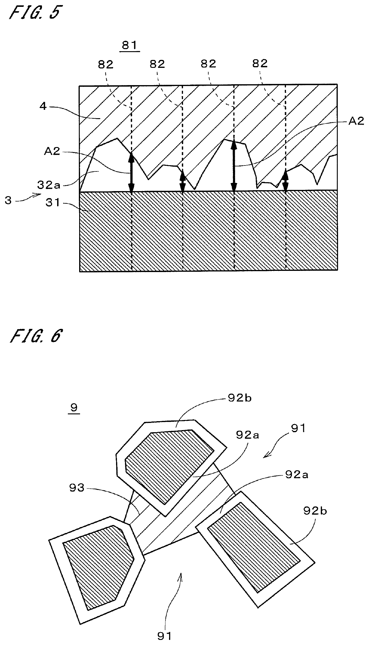
A porous material includes aggregate particles and a binding material. In the aggregate particles, oxide films containing cristobalite are provided on surfaces of particle bodies that are silicon carbide particles or silicon nitride particles. The binding material contains cordierite and binds the aggregate particles together in a state where pores are provided therein. The mass ratio of the cordierite to the whole of the porous material is in the range of 10 to 40 mass %. The oxide films that exist between the particle bodies and the binding material have a thickness less than or equal to 0.90 μm.

Description

TECHNICAL FIELD[0001]The present invention relates to a porous material, a cell structure, and a method of producing a porous material.BACKGROUND ART[0002]Porous materials produced by binding aggregate particles such as silicon carbide particles together with a binding material that contains cordierite have excellent properties such as high thermal shock resistance. For example, Japanese Patent No. 5,922,629 discloses a porous material characterized in that its binding material contains crystalline cordierite and cerium or zirconium elements and that the mass ratio of the binding material to the total mass of the aggregate and the binding material falls within a predetermined range. Such a porous material is molded into a honeycomb structure whose interior is partitioned into a plurality of cells by partition walls, and is used in, for example, a catalyst carrier or a diesel particulate filter (DPF).[0003]Incidentally, the honeycomb structure is exposed to high-temperature exhaust g...

Claims


Application Information

Patent Timeline
Patent Type & Authority Patents(United States)
IPC IPC(8): C04B35/565C04B35/587C04B35/63C04B38/00C04B35/195
CPCC04B35/565C04B35/587C04B35/6316C04B38/0009C04B38/0058C04B35/195C04B2235/3206C04B2235/3217C04B2235/3481C04B2235/3826C04B2235/3873C04B2235/602C04B2235/663C04B2235/96Y10T428/24149C04B38/067C04B38/0006C04B35/622C04B35/62605C04B35/6303C04B2235/3418C04B2235/6021C04B2235/9607C04B38/0074C04B35/62807C04B35/62897C04B2235/349C04B2235/80C04B2235/606C04B2111/2084Y02T10/12C04B35/584
Inventor TSUBOI, MIKAIZUMI, YUNIETOMITA, TAKAHIRO
Owner NGK INSULATORS LTD
Learn More