Optical shutter and display panel

Active Publication Date: 2021-12-28
NEW VISUAL MEDIA GROUP
View PDF68 Cites 0 Cited by
  • Summary
  • Abstract
  • Description
  • Claims
  • Application Information

AI Technical Summary

Benefits of technology

The present invention is a new display technology that uses reflected light to create a display with high contrast and low power consumption. The invention includes an improved single shutter configuration that is reliable and highly lightweight, making it suitable for use in cameras or other light sensitive instruments such as aerospace applications. The display panel has high contrast in direct sunlight, and it only requires ambient light because it only moves very lightweight shutters. This new display technology uses a transparent dielectric and opaque dielectric as the reflective medium, which allows for the creation of a full-color display using a traditional printed circuit board manufacturing process. The shutter has a highly reliable operation and low threshold operating voltage, which allows it to be electrically multiplexed. The shutter performs significantly better in terms of speed and weight compared to existing shades. The display has very low power consumption and can be remedied by providing external front lighting.

Problems solved by technology

A prime disadvantage as seen in existing mainstream reflective displays is limited reflectivity making the technologies inappropriate for outdoor use in direct sunlight.
Other reflective display technologies such as some forms of liquid crystal and various “electronic inks” have been tried for this application but they fall short because their background reflectivity, image darkness and color rendition are inextricably linked to the fundamental properties of their optical molecules.
Improvement of one such property degrades the other.

Method used


Image

  • Optical shutter and display panel
  • Optical shutter and display panel
  • Optical shutter and display panel

Examples


Embodiment Construction

[0048]The present invention describes improvements to the reflective display technology of the '731 Application that make it more suitable for the above uses including the ability to routinely apply multiplexing drive electronics and also making the display technology more reliable. The fundamental improvements relate to improvements in the single shutter construction and their construction into an array of shutters to form the improved display panel.

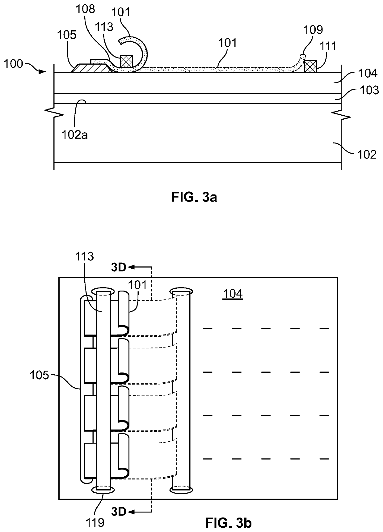
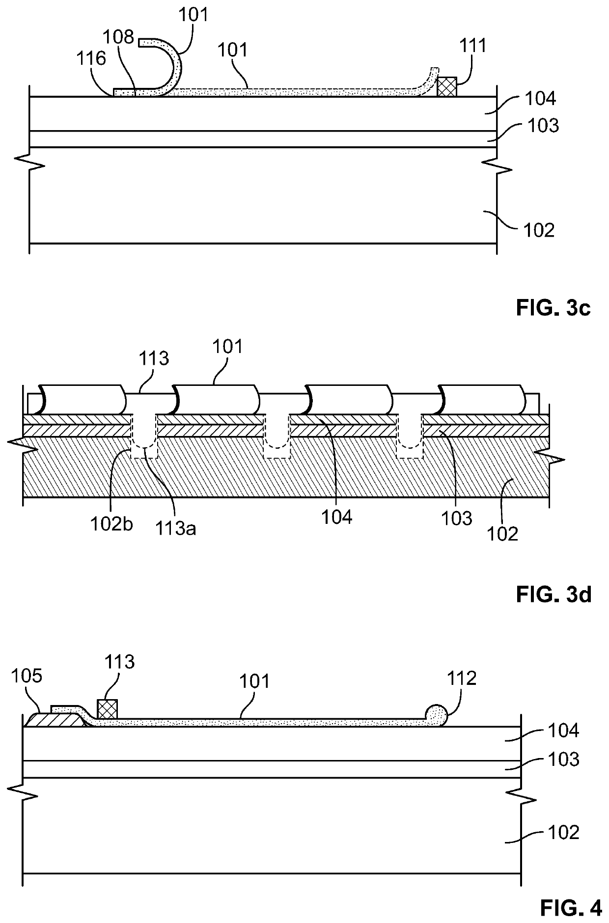
[0049]As depicted in FIGS. 3a-3d, a shutter system 100 includes a substrate 102 having a front surface 102a with a length and a width, and a conductive layer 103 on a portion of the front surface 102a of the substrate 102 with no intervening added elements or layers. A dielectric layer 104 is disposed on the conductive layer 103, and may also be disposed on the front surface 102a of the substrate 102 that is not covered by the conductive layer 103. The material of the dielectric layer 104 can be applied directly to the conductive layer ...


PUM


Abstract

A shutter system includes a substrate having a front surface with a length and a width, and a conductive layer on a portion of the front surface of the substrate; a dielectric layer disposed on the conductive layer; and an electrostatic shutter having a proximal end attached to the dielectric layer such that a portion of the shutter is in direct physical contact with the dielectric layer at a point at or adjacent the attached proximal end. The shutter is configured to transition between extended and retracted configurations. In the same or an alternative embodiment, the system includes a reinforcement configured such that when the shutter is in the extended configuration, an edge at a distal end of the shutter opposite the proximal end remains substantially parallel to the proximal end of the shutter as the shutter transitions from the extended configuration to the retracted configuration.

Description

BACKGROUND OF THE INVENTION[0001]The present invention relates to electronic lightweight optical shutters and related digital signage of all types, especially outdoor signage such as billboards, street furniture, on-site signage and traffic signage. Preferred embodiments relate to programmable signs which are highly visible especially outdoors where the sun can reduce the visibility of typical electronic displays.[0002]There is a growing use of outdoor displays, particularly in the field of advertising referred to as Digital Out Of Home (DOOH). These displays are used for advertising, public information and other applications as well. In cases where the displays are sheltered from the sunlight, displays made for consumer use such as televisions and computer monitors may be adapted for this use. However, when the displays are exposed to the outdoors and sunlight, consumer display products don't have enough contrast to be seen in that environment since the sunlight reduces the contras...

Claims


Application Information

Patent Timeline
IPC IPC(8): G09F9/37G06F1/16G09G3/34F21V14/08F21V14/00
CPCG09F9/372G06F1/1609G09G3/3433F21V14/006F21V14/08G09G2300/026
Inventor SCHLAM, ELLIOTT
Owner NEW VISUAL MEDIA GROUP
Why Eureka
Try Eureka