Sensing circuit for OLED driver and OLED driver using the same

a technology of sensing circuit and driver, which is applied in the direction of diodes, instruments, semiconductor devices, etc., can solve the problems of voltage-to-current conversion behavior, higher circuit cost, and mismatch in the luminous efficiency of oled lb>1/b>

Active Publication Date: 2021-12-21
NOVATEK MICROELECTRONICS CORP
View PDF33 Cites 0 Cited by
  • Summary
  • Abstract
  • Description
  • Claims
  • Application Information

AI Technical Summary

Benefits of technology

[0007]It is therefore an objective of the present invention to provide a sensing circuit for an organic light-emitting diode (OLED) driver, where the capacitor in the sensing circuit may be protected, to prevent an unpredictably high or low sensing voltage from being received by the capacitor.

Problems solved by technology

However, in the OLED panel 10, the driving TFT M1 in different subpixels may possess an error or mismatch in the device parameter, which may result in different voltage-to-current conversion behaviors.
In addition, there may also be a mismatch in the luminous efficiency of the OLED L1.
The great number of capacitors occupy a large circuit area and thus require higher circuit costs.
However, the panel defect may result in an unpredictable sensing voltage transmitted to the sensing circuit.
This unpredictable sensing voltage may reach up to the power supply voltage 18V or down to the ground voltage 0V, causing the capacitor in the sensing circuit to be burnt out.

Method used


Image

  • Sensing circuit for OLED driver and OLED driver using the same
  • Sensing circuit for OLED driver and OLED driver using the same
  • Sensing circuit for OLED driver and OLED driver using the same

Examples


Embodiment Construction

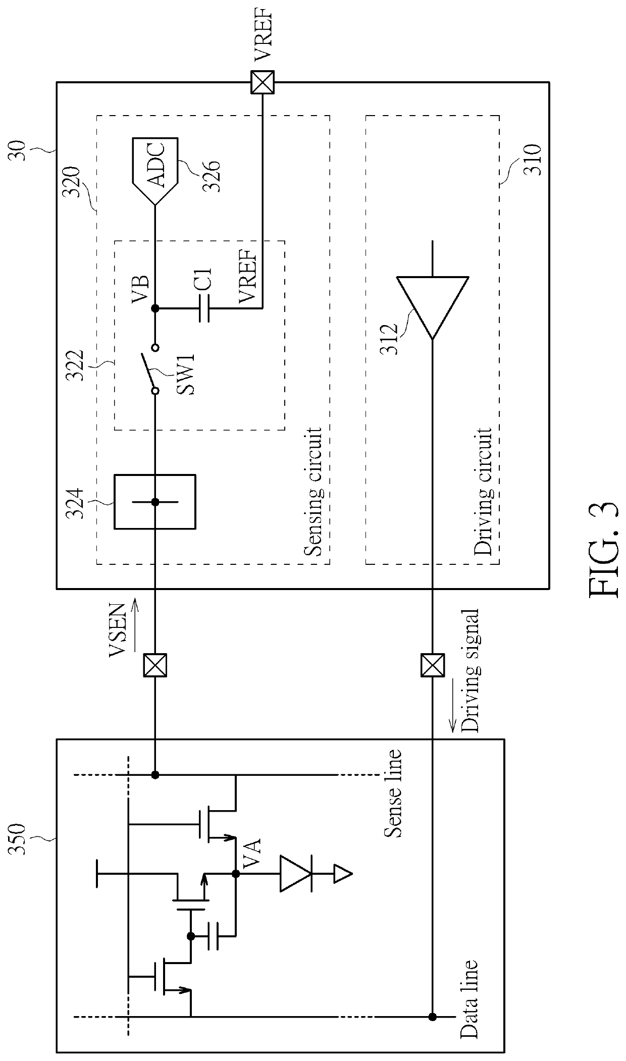
[0017]FIG. 3 is a schematic diagram of a source driver 30 according to an embodiment of the present invention. The source driver 30 includes a driving circuit 310 and a sensing circuit 320. A subpixel 350 of an organic light-emitting diode (OLED) panel is not included in the source driver 30 but illustrated in FIG. 3 to facilitate the illustration. As shown in FIG. 3, the subpixel 350 includes an OLED and three transistors (e.g., thin-film transistors (TFTs)) and one capacitor as a 3T1C structure. Those skilled in the art should understand that the present invention is applicable to an OLED panel having any structure and that shown in FIG. 3 is one of various implementations of the subpixel structure.

[0018]The driving circuit 310 includes an output driver 312, for outputting display data to the subpixel 350 during the display period. During the sensing period, the driving circuit 310 is configured to transmit a driving signal to the data line of the subpixel 350. The sensing circuit...


PUM

PropertyMeasurementUnit
sensing voltageaaaaaaaaaa
voltageaaaaaaaaaa
voltageaaaaaaaaaa

Abstract

A sensing circuit for an organic light-emitting diode (OLED) driver includes a sample and hold circuit and a clamping circuit. The sample and hold circuit includes a capacitor. The clamping circuit, coupled to the sample and hold circuit, is configured to clamp a sensing voltage received by the sample and hold circuit to conform to a withstand voltage of the capacitor.

Description

BACKGROUND OF THE INVENTION1. Field of the Invention[0001]The present invention relates to a sensing circuit for an organic light-emitting diode (OLED) driver, and more particularly, to a sensing circuit for the OLED driver which is capable of sensing parameters of pixel elements in an OLED panel.2. Description of the Prior Art[0002]An organic light-emitting diode (OLED) is a light-emitting diode (LED) in which the emissive electroluminescent layer is a film of organic compound, where the organic compound emits light in response to an electric current. OLEDs are widely used in displays of electronic devices such as television screens, computer monitors, and portable systems such as mobile phones, handheld game consoles and personal digital assistants (PDAs). An active matrix OLED (AMOLED), which is driven by a thin-film transistor (TFT) and contains a storage capacitor that maintains the pixel states to enable large size and large resolution displays, becomes the mainstream of the O...

Claims


Application Information

Patent Timeline
Patent Type & Authority Patents(United States)
IPC IPC(8): G09G3/32G09G3/3258H01L27/32H01L27/12
CPCG09G3/3258H01L27/1214H01L27/3209G09G2300/0842G09G2310/0294G09G3/3208G09G2330/12G09G3/006G09G3/3291G09G2320/029H01L27/1255H10K59/1216H10K59/32
Inventor CHENG, JHIH-SIOUTSENG, PO-YULIANG, KEKO-CHUNHUANG, JU-LINCHOU, CHIH-HSIEN
Owner NOVATEK MICROELECTRONICS CORP
Why Eureka
Try Eureka