Sports ball with controllable trajectory
a technology of trajectory control and sports balls, applied in the field of sports balls, can solve the problems of increased failure risk, increased size and portability, and achieve the effect of less traction and greater traction
- Summary
- Abstract
- Description
- Claims
- Application Information
AI Technical Summary
Benefits of technology
Problems solved by technology
Method used
Image

Examples
example 1
Ball of the Invention
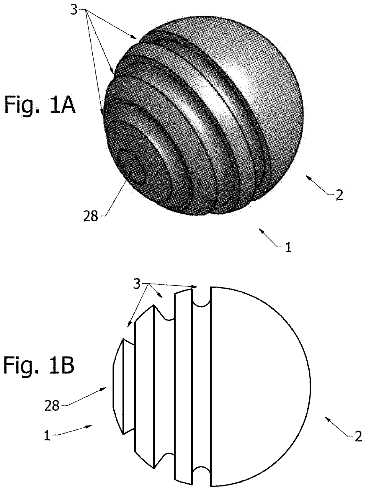
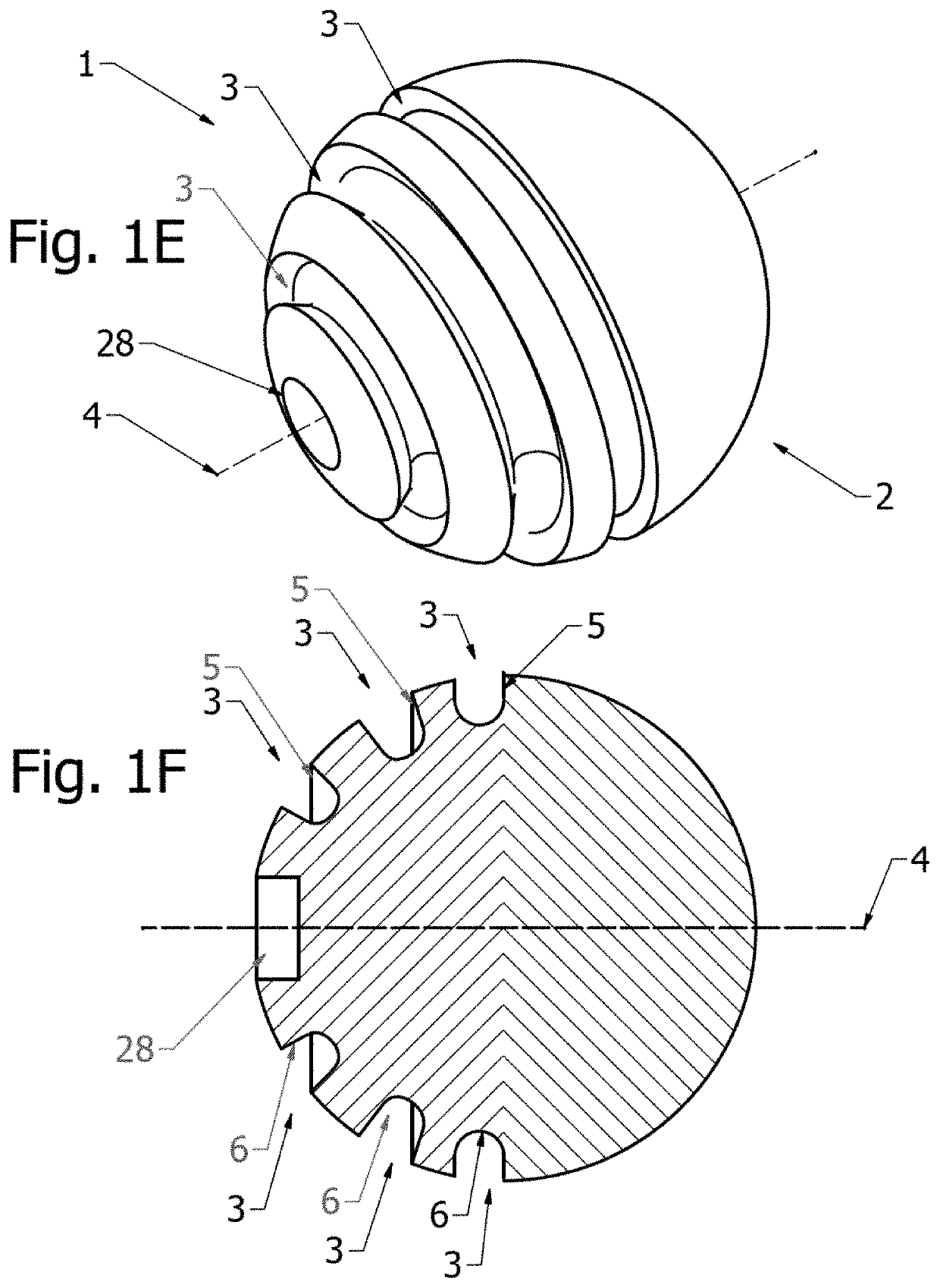
[0122]FIG. 1A depicts a useful ball of the invention. The ball comprises a first hemisphere 1 and a second hemisphere 2. The first hemisphere 1 comprises a plurality (e.g. 3) of arcuate grooves 3 (with sidewalls 5, 6) positioned about respective positions. At the surface of the ball, the groove surface edges are parallel to each other (the edges of respective grooves are annular rings laying on parallel planes which are parallel to a plane comprising the equator that joins the first hemisphere 1 and the second hemisphere 2). It is noted that, unless specifically stated, the terms plane, equator, axis, and pole are imaginary reference geometries and are not meant to indicate that the ball includes an additional structure providing the geometry.
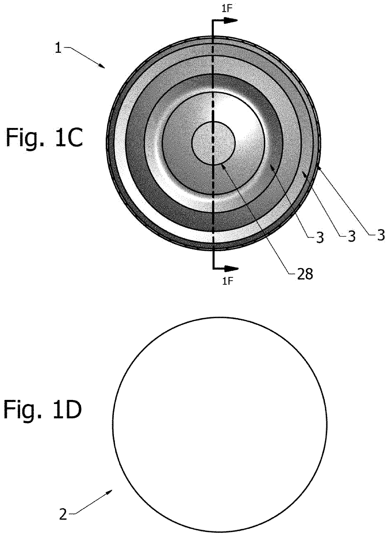
[0123]Each of the arcuate grooves 3 completely surround the ball, as shown in FIG. 10, and have a “U” shape, as shown in FIG. 1F.
[0124]The ball further comprises a cut segment 28 having a concave surface.
[0125]The ball can ...
example 2
Method of Projecting a Ball of the Invention with Controlled Horizontal Trajectory
[0128]A ball of the invention comprising a horizontal trajectory controlling structure can be projected from a pitching machine, wherein the user can control horizontal trajectory, e.g. depending upon how the structure is oriented when the ball is loaded in a pitching machine.
[0129]As shown in FIG. 4, a pitching machine can have a drive wheel 13 that spins about an axis to generate a projecting force. For reference, the drive wheel can be imagined as having a center plane 16.
[0130]As detailed in FIG. 5A and FIG. 5B, depending upon how the ball is oriented, the pitching machine will project the ball with a trajectory that is offset laterally to one side (e.g. right, FIG. 5A) or another (e.g. left, FIG. 5B). Specifically, the ball, e.g. as detailed in Example 1, can be loaded such that the plane connecting hemisphere 1 and hemisphere 2 is aligned with the center plane 16 of the drive wheel 13, as shown i...
example 3
Method of Projecting a Ball of the Invention with Controlled Vertical Trajectory
[0132]A ball of the invention comprising a height-controlling structure can be projected from a pitching machine, whereby the user can control vertical trajectory, e.g. depending upon how the structure is oriented when the ball is loaded in a pitching machine. A hemisphere of the ball can comprise a height-controlling structure that increases or decreases traction, thus providing a ball having two hemispheres which exhibit different traction on the drive wheel of a pitching machine.
[0133]FIGS. 3A and 3B depict an example setup to practice a method of the invention. A pitching machine 12 is provided, distanced from a target, e.g. near batter 15. The pitching machine comprises a drive wheel 13, a chute 29 for loading a pitching machine ball, and a pinch plate 11 that is spaced from the wheel 13 such that the ball is slightly pinched or forced against the wheel 13 to cause the wheel 13 to project the ball. ...
PUM
 Abstract
Description
Claims
Application Information
 - Generate Ideas
- Intellectual Property
- Life Sciences
- Materials
- Tech Scout
- Unparalleled Data Quality
- Higher Quality Content
- 60% Fewer Hallucinations
Browse by: Latest US Patents, China's latest patents, Technical Efficacy Thesaurus, Application Domain, Technology Topic, Popular Technical Reports.
© 2025 PatSnap. All rights reserved.Legal|Privacy policy|Modern Slavery Act Transparency Statement|Sitemap|About US| Contact US: help@patsnap.com