Bus structure

a bus and structure technology, applied in the field of bus structures, can solve the problems of reducing the quality of the output image, and achieve the effects of reducing the traction of the moving bus structure according to the present invention, facilitating and smoothing the movable electronic part, and small fiction coefficien

Active Publication Date: 2007-08-16
INTELLECTUAL VENTURES I LLC
View PDF4 Cites 0 Cited by
  • Summary
  • Abstract
  • Description
  • Claims
  • Application Information

AI Technical Summary

Benefits of technology

[0009] Accordingly, it is one object of the present invention to propose a bus structure which provides electricity and / or electronic signal between movable electronic parts within an electric device. The present invention can make the movable electronic part move with less traction than traditional one, i.e., the movable electronic part which coupled to the bus structure according to the present invention can move much more easier than the traditional one. In addition, the structure of the bus structure according to the present invention can shield mutual interference from the stacked part of the bus structure, so the image signal through the bus structure can be transmitted without mutual interference, and the resulted image quality of the electric device can be greatly improved.
[0011] In one preferred embodiment of the present invention, the plurality of soft buses are side by side placed, and every two adjacent soft buses are stacked together with a soft separation layer sandwitched therebetween. According to one of the preferred embodiments of the present invention, the soft separation layer can be made of foam material that possess smaller coefficient of fiction to the surface of soft bus than that between the soft buses, besides, the soft separation layer adheres to one of the two adjacent soft buses. So the traction from the moving bus structure according to the present invention is greatly reduced.
[0012] Accordingly, the bus structure in the present invention utilizing the soft separation layer makes it easier and smoother for the movable electronic part to move freely, and the adoption of signal wires greatly reduce the interference (such as cross talk) to the image signal, thus the quality of the resulted image is greatly improved.

Problems solved by technology

Furthermore, because of the close attachment of the soft buses, the signals transmitted in the soft buses may interfere with each other, and the quality of the output image will thus be reduced.

Method used


Image

  • Bus structure
  • Bus structure
  • Bus structure

Examples


Embodiment Construction

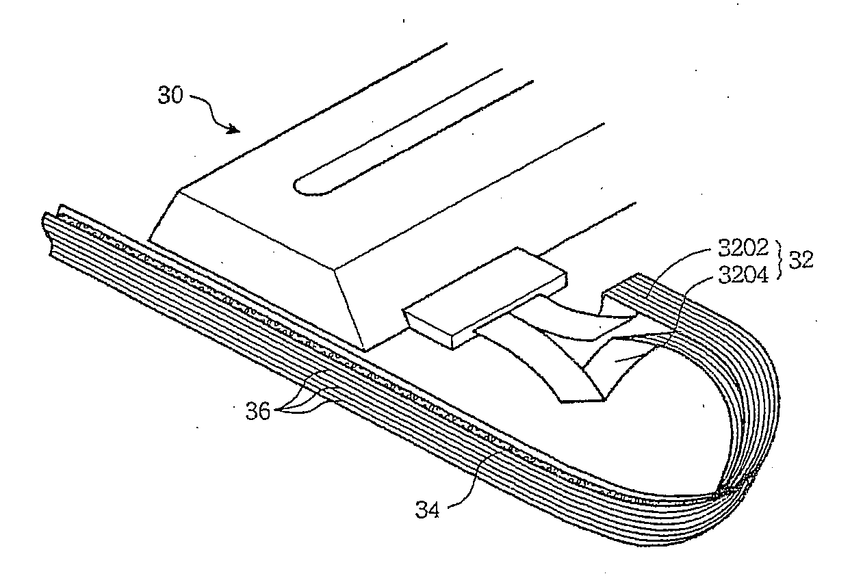
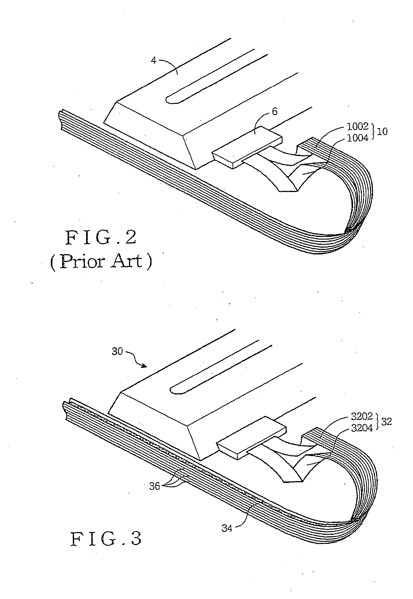
[0017] As schematically illustrates in FIG. 3, the perspective view of the bus structure 32 in accordance with a preferred embodiment of the present invention is coupled to the movable electronic part 30, in which, the bus structure 32 provides a path for power transmission and / or electronic signal communication to the moveable electronic part 30. Besides, in a foldable electric device, the bus structure 32 according to the preferred embodiment of the present invention can be used to provide power and signal communication between two or more separate parts of the foldable electric device.

[0018] As shown in FIG. 3, the bus structure 32 according to one preferred embodiment of the present invention includes a soft separation layer 34 and a plurality of soft buses, e.g., a first soft bus 3202 and a second soft bus 3204. In one end of the bus structure 32, it splits in longitude to form the first soft bus 3202 and the second soft bus 3204, in addition, the soft separation layer 34 is s...


PUM


Abstract

A bus structure includes multiple soft buses and a soft separation layer. These multiple soft buses are stacked side by side each other. The soft separation layer is sandwitched between two adjacent soft buses.

Description

BACKGROUND OF THE INVENTION [0001] (1) Field of the Invention [0002] The disclosure relates to a bus structure, and more particularly to a bus structure utilized in a scanning device. [0003] (2) Description of the Prior Art [0004] In order to transmit electric signal or energy, bus structure is widely used in electric device, for example, within a foldable electric device, a bus structure is often utilized to couple one separate part to the other, or to a movable part. Especially when the electric signal or energy is transmitted between two relatively motioning parts of an electric device, the flexible feature of a bus structure enables the electric device to operate smoothly. [0005] The structure of a scanner is schematically shown in FIG. 1. As illustrated in FIG. 1, the scanner 2 includes a servo-controlled tube lamp 4, a circuit board 6 and a soft bus 8. The tube lamp 4 projects light on the scanned object, and an image sensor generating an image signal responding to the reflect...

Claims


Application Information

Patent Timeline
Patent Type & Authority Applications(United States)
IPC IPC(8): H05K1/00
CPCH04N1/00519H04N1/1017H04N1/193H05K2201/09109H05K1/144H05K1/147H04N2201/0081
Inventor HUANG, KUO-CHINGCHANG, YU-CHENG
Owner INTELLECTUAL VENTURES I LLC
Why Eureka
Try Eureka