Heat shield fastening means

Active Publication Date: 2021-12-14
MAN NUTZFAHRZEUGE AG
View PDF20 Cites 0 Cited by
  • Summary
  • Abstract
  • Description
  • Claims
  • Application Information

AI Technical Summary

Benefits of technology

This invention describes an apparatus with a heat shield that can be easily attached to a component without damaging the heat shield during thermal expansion. The attachment is made with a simple construction and prevents damage to the heat shield. The heat shield can slide on the fastening region relative to the component and the fastening element, compensating for different thermal expansions and preventing plastic deformation and damage to the heat shield. The attachment is made with a shoulder that allows for a slidable fastening, reducing assembly complexity and costs. In one design variant, the fastening element is supported directly on the shoulder, and a gap is formed between the outer face of the heat shield and the fastening element to enable slidable fastening. The gap is small and prevents plastic deformation of the heat shield, ensuring proper heat transfer and protection.

Problems solved by technology

Here, plastic deformations and damage of the heat shield can occur.

Method used


Image

  • Heat shield fastening means
  • Heat shield fastening means

Examples


Embodiment Construction

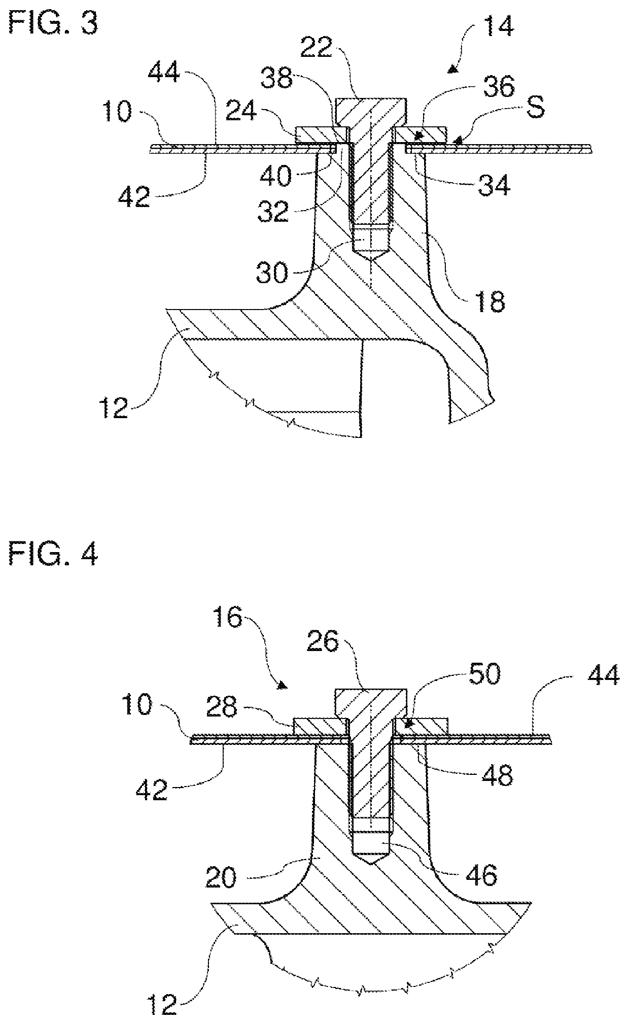
[0037]The embodiments which are shown in the figures correspond at least partially, with the result that similar or identical parts are provided with the same reference numerals and, in order to explain them, reference is also made to the description of the other embodiments and / or figures, in order to avoid repetitions.

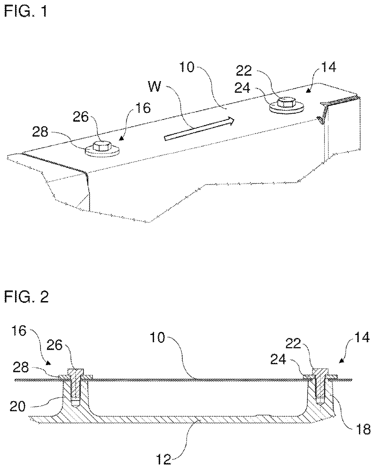
[0038]FIGS. 1 and 2 show a heat shield 10. The heat shield 10 is attached on component 12 (see FIG. 2). The component 12 is a heat source which is to be shielded by the heat shield 10. The component 12 can be, for example, an exhaust gas routing element, for example an exhaust gas pipe, an exhaust gas manifold, a turbocharger or an exhaust gas aftertreatment system, of an internal combustion engine. The internal combustion engine can be included in a motor vehicle, in particular a commercial vehicle, for example a lorry or an omnibus.

[0039]The heat shield 10 can be configured in one layer or in multiple layers. The heat shield 10 is preferably produced from a metal.

[...


PUM


Abstract

An apparatus for shielding hot regions, in particular of an internal combustion engine, includes a heat shield with a through hole. The apparatus has a component, in particular a heat source, with a fastening region which has a receptacle and a shoulder which surrounds the receptacle at least partially. The shoulder extends through the through hole of the heat shield. The apparatus has a fastening element, in particular a screw, which fastens the heat shield to the fastening region, the fastening element being supported on the shoulder, extending through the through hole of the heat shield, and being fastened in the receptacle.

Description

TECHNICAL FIELD[0001]The invention relates to an apparatus for shielding hot regions, in particular of an internal combustion engine.BACKGROUND[0002]Heat shields can be used for shielding hot regions, for example, in the case of internal combustion engines of motor vehicles, in particular in the region of the exhaust gas section. The heat shields serve to protect temperature-sensitive components and assemblies. Here, the heat shields can also improve the sound insulation.[0003]Heat shields are usually three-dimensionally shaped structural components which have at least one metallic sheet layer. Here, the three-dimensional shape of the at least one metallic sheet layer usually results from the shape of the components which are to be shielded with respect to one another and from their spacing from one another.[0004]The attachment of the heat shield to the component usually takes place by means of a punctiform connection. To this end, the metallic sheet layer or all metallic sheet laye...

Claims


Application Information

Patent Timeline
IPC IPC(8): B60R13/08F01N13/10F01N13/18F01N13/14F02B77/11
CPCB60R13/0876B60R13/0815F01N13/102F01N13/14F01N13/1805F01N13/1811F01N13/1855F02B77/11F01N2260/20F01N2450/24
Inventor HERZIG, JÜRGENSIMON, WOLFGANGLIENERT, ALEXANDER
Owner MAN NUTZFAHRZEUGE AG
Why Eureka
Try Eureka