
Method and apparatus for displaying virtual reality image

a virtual reality and image technology, applied in the field of methods and apparatus for displaying virtual reality images, can solve problems such as difficulty in providing two modes, and achieve the effect of preventing users from colliding

Active Publication Date: 2021-11-02
KOREA INST OF SCI & TECH
View PDF13 Cites 1 Cited by
  • Summary
  • Abstract
  • Description
  • Claims
  • Application Information

AI Technical Summary

Benefits of technology

The present invention is a method for preventing a user from hitting into an obstacle when they approach it while wearing virtual reality glasses. The method includes making the obstacle more visible as the user gets closer to it. This is done by adjusting the display device to show more light incident from the outside, which makes the obstacle appear brighter. Overall, this helps to keep the user away from the obstacle and prevents accidents while wearing virtual reality glasses.

Problems solved by technology

Thus, it is difficult to provide the two modes.

Method used


Image

  • Method and apparatus for displaying virtual reality image
  • Method and apparatus for displaying virtual reality image
  • Method and apparatus for displaying virtual reality image

Examples


first embodiment

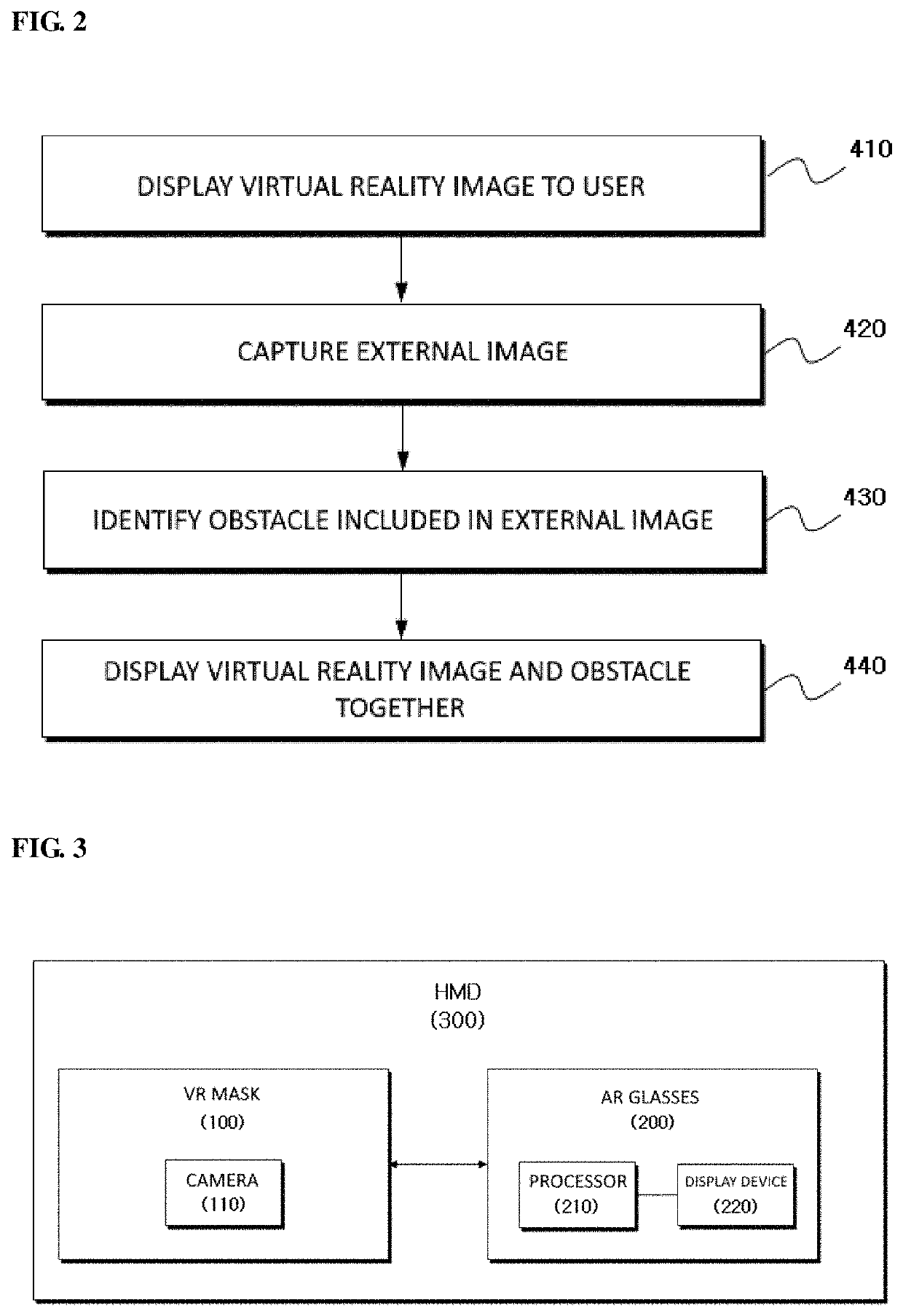
[0066]FIG. 2 is a flowchart illustrating a method of displaying a virtual reality image according to a Referring to FIG. 2, a head-mounted display (HMD) 300 may display a virtual reality image and an obstacle 500 together to prevent collision with the obstacle 500 and the user.

[0067]The HMD 300 may be a VR device and may be a coupling of a VR mask 100 and augmented reality (AR) glasses 200. The HMD 300 may be expressed as a virtual reality image display device or the like.

[0068]In operation 410, the HMD 300 displays a virtual reality image to a user. The user cannot see the outside while viewing the virtual reality image because external light is blocked by the HMD 300.

[0069]In operation 420, the HMD 300 captures an external image. For example, the VR device or the VR mask 100 includes a camera 110, and the camera 110 captures an external image while the user views the virtual reality image. The camera 110 may capture an image in the user's gaze direction.

[0070]In operation 430, th...

second embodiment

[0088]FIG. 5 is a diagram illustrating a polarizing plate 120 of another VR mask 100′ according to a The VR mask 100′ includes the polarizing plate 120.

[0089]The polarizing plate 120 adjusts the amount of light incident from the outside through transmission or blocking by a window. When the polarizing plate 120 is closed, light incident from the outside is blocked so that the user who wears the VR mask 100′ cannot see the outside. When the polarizing plate 120 is opened, light incident from the outside is allowed so that the user who wears the VR mask 100′ can see the outside.

[0090]When the user who wears the VR mask 100′ views a virtual reality image, the user may collide with an external obstacle 500 because the user cannot see the outside. Accordingly, when the external obstacle 500 approaches the user, the polarizing plate 120 is opened so that the user can see and avoid the obstacle 500.

[0091]FIG. 6 is a diagram illustrating that the VR mask 100′ adjusts the amount of transmit...


PUM


Abstract

A user wears a virtual reality mask (VR mask) (100) and then watches a virtual reality image. The VR mask (100) blocks light incident from the outside. When the user wears the VR mask (100), the user cannot discover an obstacle (500) positioned outside the VR mask (100). The user may collide with the obstacle (500) and may be injured by the obstacle (500). Accordingly, in order to prevent injury to the user who uses the VR mask (100), it is necessary to make the user recognize the obstacle (500) positioned outside the VR mask (100). In order to recognize an obstacle, a virtual reality image and the obstacle may be displayed together, or the amount of light incident from the outside may be adjusted.

Description

CROSS-REFERENCE TO RELATED APPLICATION[0001]This application claims priority to and the benefit of Korean Patent Application Nos. 2019-0177549 and 2019-0177550, filed on Dec. 30, 2019, the disclosures of which are incorporated herein by reference in its entirety.BACKGROUND1. Field of the Invention[0002]The present disclosure relates to a method and apparatus for displaying a virtual reality image, and particularly, to a method of displaying a virtual reality image using a virtual reality mask (VR mask), augmented reality glasses (AR glasses), a VR device, or a head-mounted display (HMD), etc.2. Discussion of Related Art[0003]Various content items are being produced using virtual reality images. Virtual reality (VR) devices provide users with a virtual environment rather than a real environment so that the users may experience a new environment.[0004]Augmented reality (AR) glasses provide users with a real environment and a virtual image to provide the users with information that can...

Claims


Application Information

Patent Timeline
Patent Type & Authority Patents(United States)
IPC IPC(8): G06T19/00G06F3/01G06T1/20G06T15/20G01P13/00G06K9/00G02B5/30
CPCG06T19/006G01P13/00G06F3/011G06K9/00664G06T1/20G06T15/20G02B5/30G06F3/012G02B27/0176G02B2027/0138G02B2027/0134G06T19/20G06T2219/2024G06V20/20G06V20/10
Inventor PARK, MIN CHULKANG, JI HOONCHOI, JUN YONGKO, KYULAHN, DAE HWANKIM, DAE YEONKO, HYUN WOO
Owner KOREA INST OF SCI & TECH
Learn More