Radar system with angle error determination function and method thereof

a technology of angle error determination and radar system, which is applied in the field of radar systems, can solve the problems of image detection system, detection failure or misjudgment, and easy deviation of detection direction and angle of radar, and achieve the effect of maintaining accuracy of fcw system, facilitating safe driving, and fast calibration function

Active Publication Date: 2021-10-19
CUBTEK INC
View PDF25 Cites 1 Cited by
  • Summary
  • Abstract
  • Description
  • Claims
  • Application Information

AI Technical Summary

Benefits of technology

[0014]With such configuration, when the radar angle changes, the system of the present invention is able to automatically adjust the radar angle, thus making the radar angle indicating the object position displayed by the radar device be consistent with the image angle of the camera device. Therefore, the inconvenience of a conventional radar angle calibration operation, which shall be operated by the mechanic at an automobile maintenance plant, is resolved, achieving a fast calibration function.
[0015]Also, during the vehicle driving process, the abnormality of the radar angle will be pointed out immediately, and the radar angle is calibrated in time based on the image angle of the camera device. Therefore, the accuracy of the FCW system is maintained, facilitating a safe driving.

Problems solved by technology

However, the image detection system is easily affected by weather variation to cause a detection failure or misjudge.
As a result, the detection direction and angle of the radar will easily deviate when bumping on the road or undergoing collision.
However, such radar angle adjusting apparatus is unable to be operate by general drivers.
Therefore, upon any radar angle deviation occurring, the apparatus of such patent or other radar adjusting devices have to be operated by a mechanic in an automobile maintenance plant, thus being time costing and causing the inconvenience of driver.
Also, when the radar angle changes, the position of a detected obstacle is incorrect, and the driver is unable to accurately evade the obstacle and suffers from the possibility of accident.
Therefore, if the radar angle is not immediately corrected upon the abnormality, the driving safety of driver will be threatened.

Method used


Image

  • Radar system with angle error determination function and method thereof
  • Radar system with angle error determination function and method thereof
  • Radar system with angle error determination function and method thereof

Examples


Embodiment Construction

[0023]The aforementioned and further advantages and features of the present invention will be understood by reference to the description of the preferred embodiment in conjunction with the accompanying drawings where the components are illustrated based on a proportion for explanation but not subject to the actual component proportion.

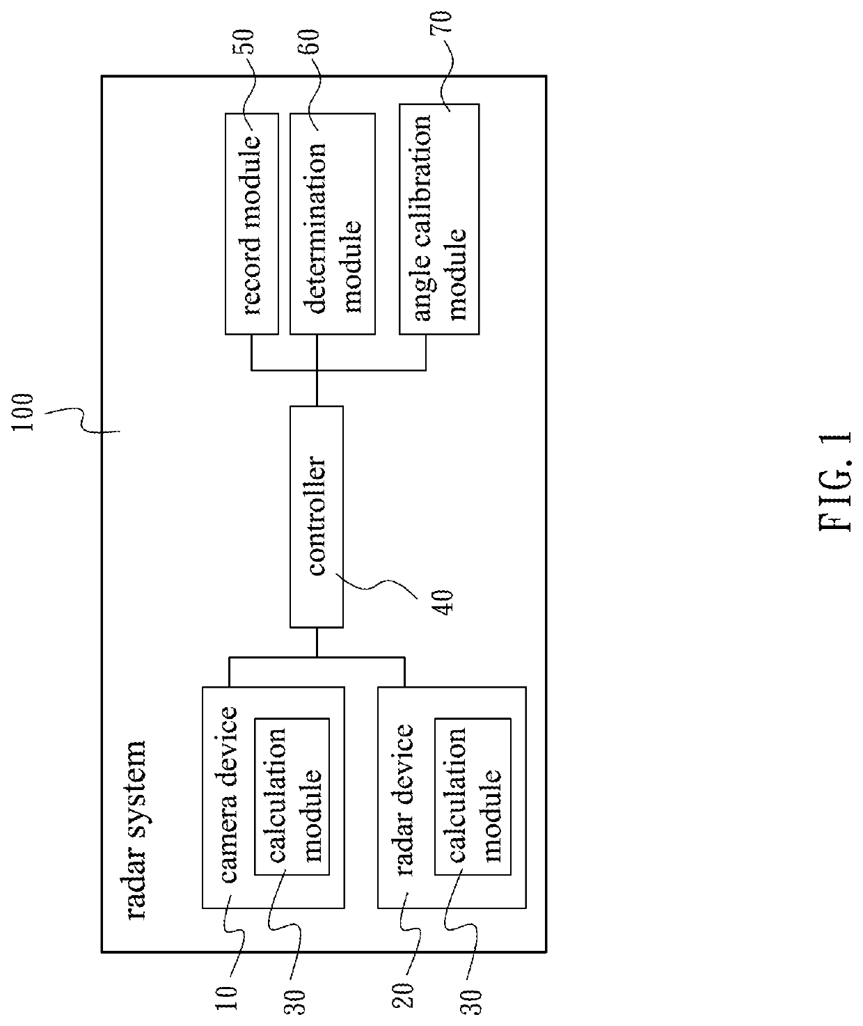
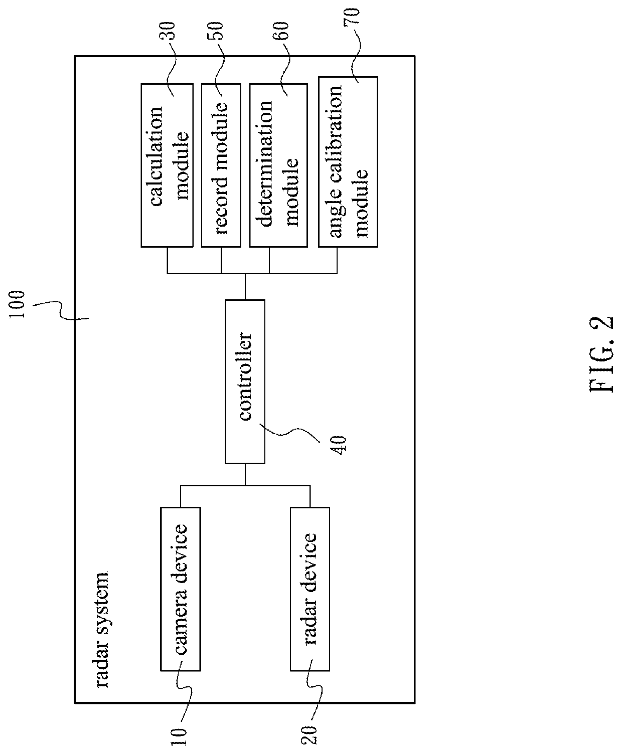
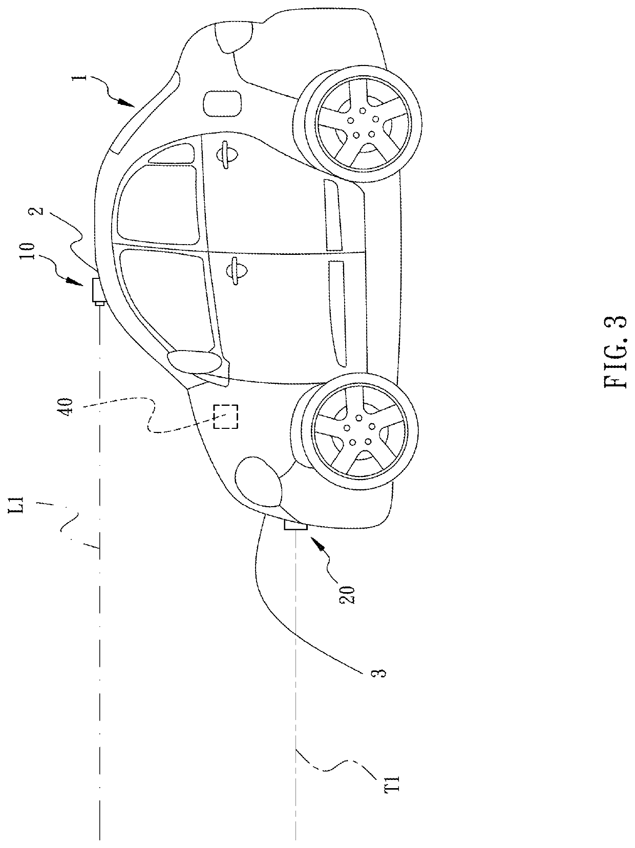
[0024]Referring to FIG. 1 to FIG. 6, a radar system 100 is provided by the present invention. Therein, FIG. 1 is a block diagram of the system in accordance with an embodiment of the present invention, and FIG. 2 is a block diagram of the system in accordance with another embodiment of the present invention. The radar system 100 comprises a camera device 10, a radar device, a calculation module 30, a record module 50, a determination module 60, and an angle calibration module 70.

[0025]The camera device 10 is disposed at a first position 2 of the vehicle 1 for capturing a surveillance image of a surveillance area around the vehicle 1. The camera device ...


PUM


Abstract

A radar system with angle error determination function and method thereof are provided. The system includes a camera device, a radar device, a calculation module, and an angle calibration module. The camera device captures a surveillance image of a surveillance area. The radar device sends a radar signal toward the surveillance area. The calculation module, according to the surveillance image, acquires an image angle of an object with respect to the vehicle in the surveillance area. Also, the calculation module acquires a radar angle of the object with respect to the vehicle which is produced according to a reflection signal generated when the radar signal meets the object. The angle calibration module, by referring to the image angle, correspondingly calibrates the radar angle. Therefore, the radar angle is immediately calibrated.

Description

BACKGROUND OF THE INVENTION1. Field of the Invention[0001]The present invention relates to radar systems, and more particularly, to a radar system with angle error determination function and method thereof.2. Description of the Related Art[0002]A forward collision warning (FCW) system is applied for detecting the obstacles in front of a vehicle by a sensor installed on the vehicle. If the system detects an obstacle existing in the warning area, the system will actively send out a warning light or warning alarm to the driver, allowing the driver to stop driving or avoid the obstacle according to the warning, thus preventing the traffic accident from happening due to inattention or vision blind spot.[0003]Current FCW systems are generally divided into image detection system and radar system. Therein, the image detection system applies the camera to acquire an image of the warning area for detecting the obstacles. However, the image detection system is easily affected by weather variat...

Claims


Application Information

Patent Timeline
Patent Type & Authority Patents(United States)
IPC IPC(8): G01S7/40G01S13/931G01S13/86
CPCG01S7/4026G01S7/40G01S13/867G01S13/931G01S7/403G01S2013/93271
Inventor YU, SAN-CHUANCHUNG, SHYH-JONGLIN, JYONG
Owner CUBTEK INC
Why Eureka
Try Eureka