
Ultralight artificial medium multilayer cylindrical lens

a technology of artificial medium and cylindrical lens, applied in the field of nanotechnology, can solve the problems of small number of applications, difficult to enter the civilian sector, difficult to apply on a large scale, etc., and achieve the effects of accurate measurement, simple and convenient fabrication techniques, and full dominance of field strength

Active Publication Date: 2021-10-12
XIAN XIAO SANTENNA TECH CO LTD
View PDF17 Cites 0 Cited by
  • Summary
  • Abstract
  • Description
  • Claims
  • Application Information

AI Technical Summary

Benefits of technology

[0011]The technical problem to be solved by the present invention is to provide a simple processing, ultralight quality, and ultra-wide frequency artificial medium multilayer cylindrical lens, to solve the defects of the existing spherical or hemispherical Luneberg lens: difficult to process, excessive quality, and narrow beam width of the vertical plane.
[0034](1) The ultralight artificial medium lens provided by the present invention changes the dielectric constant of different layers of the lens by adding a high dielectric constant material to the low dielectric constant base material, and the fabrication techniques is simple, convenient, and quick. The dielectric constant of each layer of material can be accurately measured, which overcomes the problem of mechanical deformation and inaccurate dielectric constant caused by punching in the conventional process, and there will be no gap between layers caused by secondary foaming or material shrinkage in foaming process.
[0035](2) Compared with the conventional spherical or hemispherical Luneberg lens, the artificial medium multilayer cylindrical lens provided by the invention is simpler, cylindrical instead of spherical or hemispherical is used, which used in the antenna has the characteristics of multi-beam and vertical plane pattern width.
[0036](3) The artificial medium multilayer cylindrical lens provided by the invention can be made according to the specific needs of the antenna index, and most importantly, the lens produced is ultra-light, ultra-low density, and it's total apparent density is only 0.08-0.095 g / cm3, which is lower than all artificial medium lenses in the prior art, and the lens has a characteristic of ultra-wideband (even applicable to frequencies above 28 GHz). This will greatly expand the application of the lens in the fifth generation (5G) civil and military fields, and combine with antenna technology to form an artificial medium lens antenna, particularly applicable in crowded areas and large data traffic areas.
[0037](4) The lens provided by the present invention can be applied to the field of antennas, and provides a practical carrier for constructing a multi-beam antenna. When used, the antenna unit is usually fixed on the outside of the artificial medium multilayer cylindrical lens. When compared with the conventional electronically modulated antenna, the vertical surface lobes are wider and cover, and the field strength is fully dominant in most areas. Therefore, the traditional vertical lobe electric adjustment down-tilt mechanism can be omitted, and it can fix two-dimensional scanning (horizontal and vertical surface coverage simultaneously exist) in traditional base station antenna (including the Luneberg multi-beam antenna) with wide sectorization and save a lot of energy consumption and cost, save site resources, especially suitable for crowded areas and big data traffic business areas.
[0038](5) The artificial medium multilayer cylindrical lens provided by the present invention has a simple fabrication techniques, and due to the cylindrical lens is small in volume, ultra-light in weight, and ultra-wide in frequency band, the antenna using the cylindrical lens can be applied to the military and civilian fields, overcoming the conventional antenna being too bulky or the equipment complicated is difficult to enter the shortcomings of the civilian sector.

Problems solved by technology

However, it is difficult to apply on a large scale due to the problems of asymmetric beam, isolation, loss of gain due to network loss, narrow band, etc.
However, due to the heavy weight of the Luneburg lens and the extremely complicated manufacturing process, it has long been used as a radar passive target detection, airport runway blind drop and other bands above 8 GHz.
A small number of applications are difficult to enter the civilian sector.
The traditional Luneburg ball antenna is mainly made by punching and foaming, and the process is time consuming and the product weighs too much.
The punching method is very difficult to operate in hole positioning and processing, and because of the large number of holes, there are problems such as deformation and mechanical strength during the manufacturing process, and the robustness between the parts is low, and this design can only be realized.
In fact, the efficiency of the lens antenna is very low.
There is also a certain defect in the production of the Luneburg lens by the foaming method.
If it is to be improved, the density of the material will inevitably be large and the weight will be increased.
Moreover, since the density of the foamed material is difficult to precisely control, and the foamed beads are liable to undergo secondary foaming or shrinkage, resulting in a gap between the materials, the dielectric constant is difficult to precisely control.
Like the traditional mobile communication base station antenna, the Matsine Luneburg ball antenna is also equipped with a complex vertical beam downtilt mechanism due to the narrow beamwidth of the vertical plane, which increases the operational difficulty, complexity and cost of the application.
It is difficult to control the dielectric constant of each lens layer by this method, and it is also difficult to obtain the specific dielectric constant value of each layer, and the dielectric constant can only be changed macroscopically.
Moreover, the process of opening holes in the base material is cumbersome, the drilling process is difficult, and the number of holes is large, and the deformation and mechanical strength of the material need to be considered.
However, the production process is cumbersome, and the use of the mold is complicated, and the temperature and reaction time are controlled very accurately, and it is difficult to mass-produce.
However, the use of the additive manufacturing method to manufacture the lens has certain limitations in material selection, and it is impossible to use a foam material having a very low density.
It is still difficult to have a big breakthrough.
The requirements are high and it takes a long time to prepare the mold.

Method used


Image

  • Ultralight artificial medium multilayer cylindrical lens
  • Ultralight artificial medium multilayer cylindrical lens

Examples


example 1

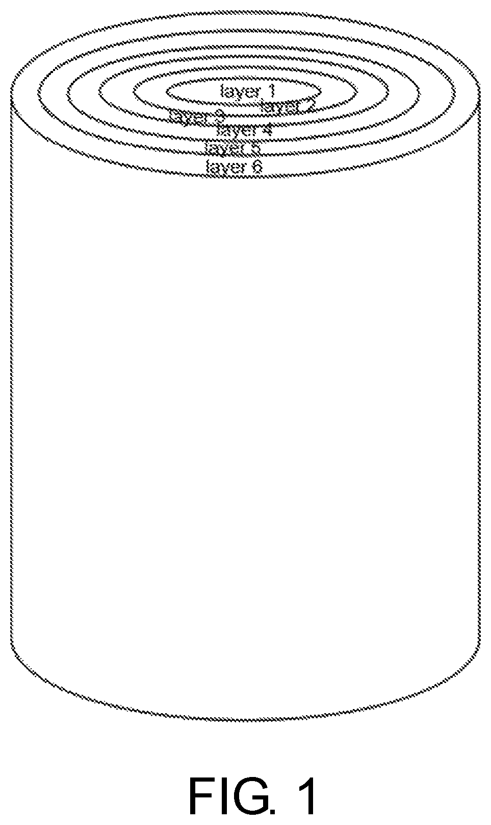
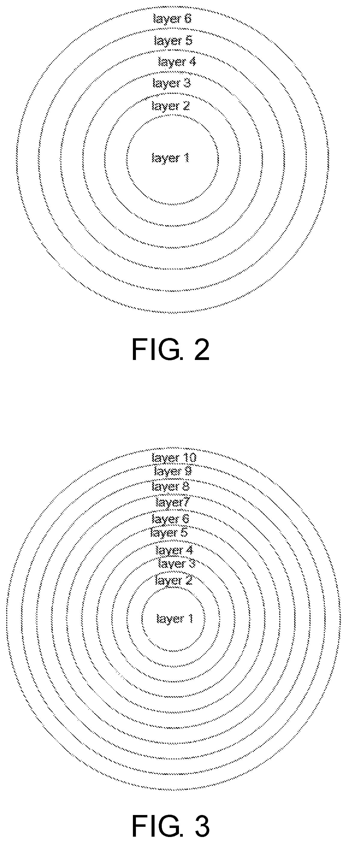
[0057]Referring to FIG. 1 and FIG. 2, in one embodiment of the present invention, a six-layer artificial medium cylindrical lens having a height of 30 cm and a diameter of 36 cm is provided. Table 1 shows specific parameters of each layer of the lens. The resulting lens has a total apparent density of only 0.092 g / cm3, ultra-low density and ultra-light weight.

[0058]

TABLE 1layerlayerlayerlayerlayerlayerlayer123456Design1.851.61.451.31.151.08dielectricconstant valueFinal dielectric1.85 + / −1.6 + / −1.45 + / −1.3 + / −1.15 + / −1.08 + / −constant value0.050.050.060.070.030.03Inside diameter—95.5156.4208.6256.9311.4(mm)Outer diameter95.4156.3208.4256.8311.2360.2(mm)

[0059]When the cylindrical lens is applied to a multi-beam antenna, due to the special action of its columnar structure on the elevation plane, a complicated electro-optic down-tilt mechanism can be omitted compared to a conventional spherical or hemispherical lens. Such as a 6-layer cylindrical lens provided by the present invention, t...

example 2

[0060]Referring to FIG. 3, in another embodiment of the present invention, a 10-layer artificial medium cylindrical lens having a height of 50 cm and a diameter of 65 cm is provided, table 2 shows specific parameters of each layer of the lens, and is finally made, the total apparent density of the lens is only 0.086 g / cm3, the density is ultra-low, the quality is ultra-light, and the application range is wider.

[0061]

TABLE 2Layerlayerlayerlayerlayerlayerlayerlayerlayerlayerlayer12345678910Design1.951.851.71.581.481.381.281.181.11.05dielectricconstantvalueFinal1.95 + / −1.85 + / −1.7 + / −1.58 + / −1.48 + / −1.38 + / −1.28 + / −1.18 + / −1.1 + / −1.05 + / −dielectric0.030.030.040.030.030.040.030.040.030.02constantvalueInside—175.7236.4293.2345.9396.9447.2496.7548.4600.4diameter(mm)Outer175.6236.3293.2345.8396.9447.1496.7548.4600.3650.1diameter(mm)

[0062]In addition, when the cylindrical lens is used to construct a multi-beam antenna in the antenna system, combined with the antenna element, a 10-beam full-...


PUM

PropertyMeasurementUnit
dielectric constantaaaaaaaaaa
apparent densityaaaaaaaaaa

Abstract

Provided in the present invention is an ultralight artificial medium multilayer cylindrical lens, comprising n concentric layers of different dielectric constants. The center cylindrical layer is expressed as layer 1 and is a solid cylinder. Layers 2 to n are in a sequentially outward nested arrangement surrounding the center cylindrical layer and respectively are n-1 concentric rings. The n concentric layers are assembled into a multilayer cylinder and are characterized in that the dielectric constants of the n concentric layers gradually decrease from layer 1 to layer n and vary specifically between 2.05 to 1.05. The n concentric layers are made of a base material of low dielectric constant added with a material of high dielectric constant and low specific gravity. The lens so manufactured has a total apparent density of 0.08-0.095 g / cm3.

Description

CROSS-REFERENCE TO RELATED APPLICATION[0001]This application is a 371 of international application of PCT application serial no. PCT / CN2018 / 100882, filed on Aug. 16, 2018, which claims the priority benefits of China application no. 201710713195.8, filed on Aug. 18, 2017 and China application no. 201711122204.2, filed on Nov. 14, 2017. The entirety of each of the above-mentioned patent applications is hereby incorporated by reference herein and made a part of this specification.BACKGROUNDTechnical Field[0002]The present invention relates to the field of antenna engineering technology, and more particularly, to an ultralight artificial medium multilayer cylindrical lens.Description of Related Art[0003]With the rapid expansion of demand in the wireless field of mobile communication 4G, 5G, MIMO, satellite communications, radar, electronic warfare, etc., new technical requirements have also been proposed for antennas as wireless gateways. In order to meet the requirements of high gain, ...

Claims


Application Information

Patent Timeline
Patent Type & Authority Patents(United States)
IPC IPC(8): H01Q15/08
CPCH01Q15/08C08L23/06C08L25/06C08L27/06C08L2203/14
Inventor XIAO, LIANG YONGREN, YU WENWANG, JIAN QINGWANG, YA
Owner XIAN XIAO SANTENNA TECH CO LTD
Learn More