Retractable ladder
a technology of retractable ladders and supports, which is applied in the direction of ladders, building construction, construction, etc., can solve the problems of unstable and reliable connection between the inner leg and the outer leg of the stretchable ladder, and achieve the effects of reducing welding costs, reducing risk, and improving the stability of the ladder
- Summary
- Abstract
- Description
- Claims
- Application Information
AI Technical Summary
Benefits of technology
Problems solved by technology
Method used
Image

Examples
first embodiment
The First Embodiment
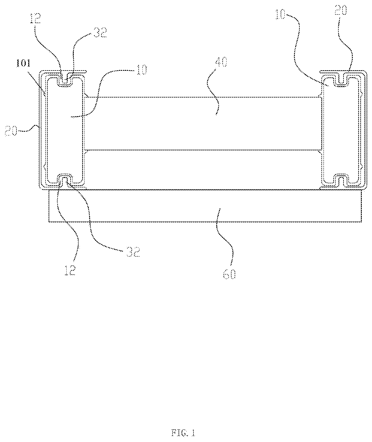
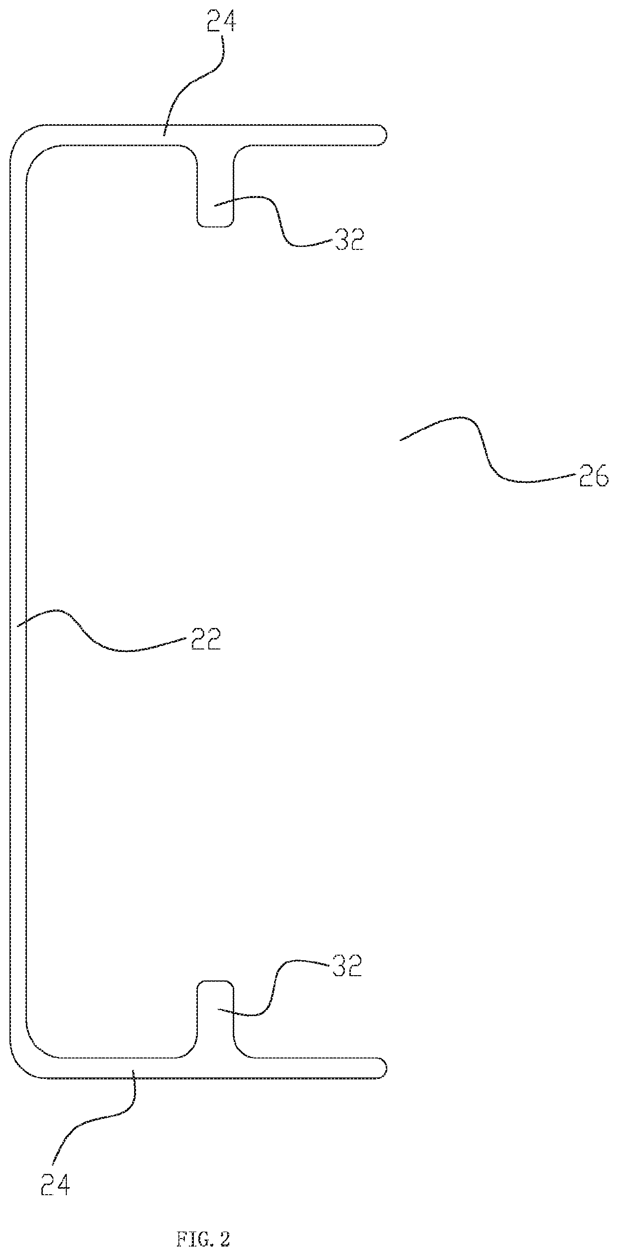
[0018]Please referring to FIG. 1 and FIG. 2, the stretchable ladder comprises two inner leg bars 10, an inner cross bar 40 connecting the two inner leg bars 10, two outer leg bars 20, an outer cross bar 60 connecting the two outer leg bars 20; the two outer leg bars 20 are respectively slidably connected to the two inner leg bars 10. The stretchable leg of the stretchable ladder of the present invention comprises the inner leg bar 10 and the outer leg bar 20. The section of the outer leg bar 20 is [ shaped, the outer leg bar 20 comprises a bottom plate 22 and two side plates 24, two side plates 24 are symmetrically disposed at the two ends of the bottom plate 22, the side edge of the outer leg bar forms an opening 26. The inner leg bar 10 is a closed hollow tube. The outer leg bar 20 is sleeved on the inner leg bar 10, the inner leg bar 10 and the outer leg bar 20 can slide relatively.
[0019]This embodiment further comprises a lock structure disposed at the outer ...
second embodiment
The Second Embodiment
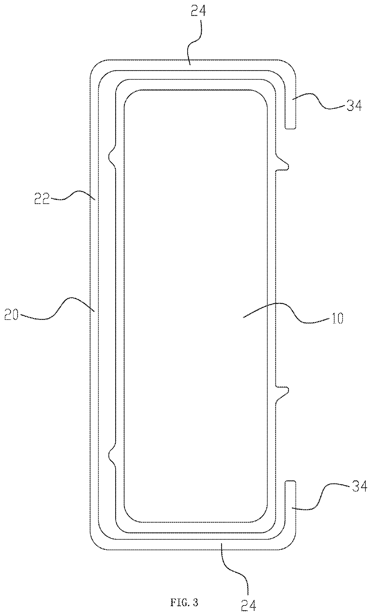
[0021]Referring to FIG. 3, this embodiment differs from the first embodiment in that: the lock structure comprises two stop plate 34, the stop plates 34 are respectively disposed at the two side plates 24. The stop plate 34 is disposed at the end of the side plate 24 away from the bottom plate 22. The cross section of the outer leg bar 20 is C shaped.
third embodiment
The Third Embodiment
[0022]Referring to FIG. 4, this embodiment differs from the first embodiment in that: the lock structure comprises two lock hooks 36 disposed at the inner side of the bottom plate 22, the inner leg bar 10 is disposed with two curve hooks 14 corresponding to the two lock hooks 36, and the two lock hooks 36 are slidably locked to the two curve hooks 14. The two lock hooks 36 and the two curve hooks 14 are symmetrical. The outer leg bar 20 comprises the bottom plate 22 and two straight side plates 24, and the two straight side plates 24 are disposed on two ends of the bottom plate 22. The inner leg bar 10 comprises a closed frame 102. The two straight side plates 24 are parallel to and are separated from sides of the closed frame 102 adjacent to the two straight side plates 24. A first portion 1021 of the closed frame 102 adjacent to the bottom plate 22 is disposed in a frame 200 having an inner opening 201 defined by the bottom plate 22 and the two straight side pl...
PUM
 Abstract
Description
Claims
Application Information
 - R&D
- Intellectual Property
- Life Sciences
- Materials
- Tech Scout
- Unparalleled Data Quality
- Higher Quality Content
- 60% Fewer Hallucinations
Browse by: Latest US Patents, China's latest patents, Technical Efficacy Thesaurus, Application Domain, Technology Topic, Popular Technical Reports.
© 2025 PatSnap. All rights reserved.Legal|Privacy policy|Modern Slavery Act Transparency Statement|Sitemap|About US| Contact US: help@patsnap.com