
Fuel system control for refrigeration unit engine

a technology for fuel system control and refrigeration unit engines, applied in electrical control, machines/engines, tractors, etc., can solve problems such as damage to the overall transport refrigeration system

Active Publication Date: 2021-09-14
CARRIER CORP
View PDF45 Cites 1 Cited by
  • Summary
  • Abstract
  • Description
  • Claims
  • Application Information

AI Technical Summary

Benefits of technology

The system effectively prevents damage by automatically shutting off fuel supply during detected issues, ensuring the refrigeration unit's operation is protected from crashes, leaks, and engine stalls, thereby maintaining the integrity of the refrigeration system and the perishable goods being transported.

Problems solved by technology

Problems in the fuel system may lead to damage to the overall transport refrigeration system and thus a system for monitoring the fuel system is desired.

Method used


Image

  • Fuel system control for refrigeration unit engine
  • Fuel system control for refrigeration unit engine
  • Fuel system control for refrigeration unit engine

Examples


Embodiment Construction

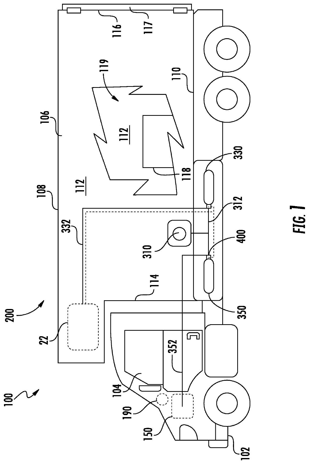
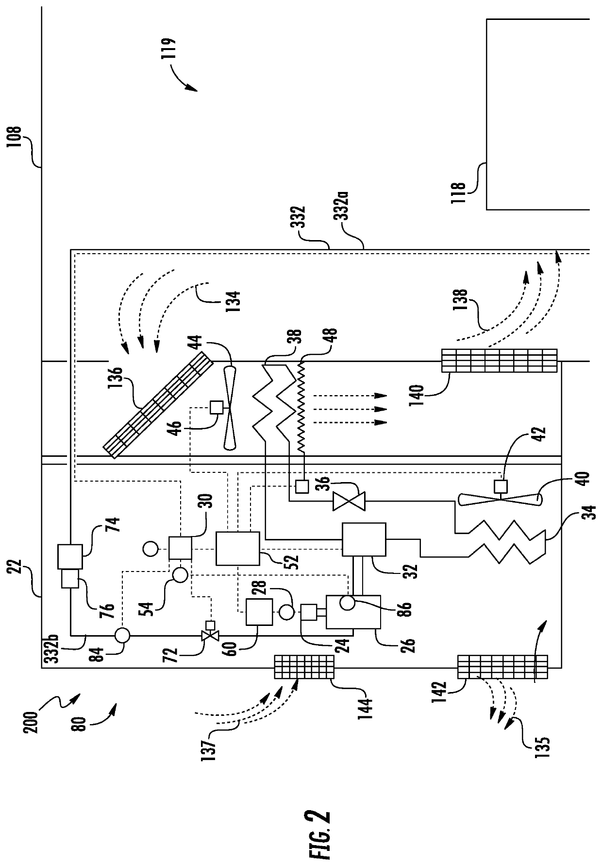
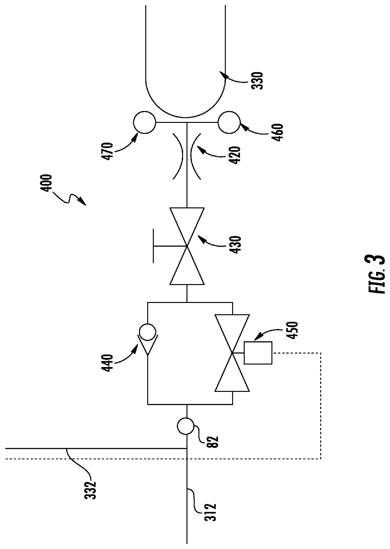
[0043]Referring to FIGS. 1-4, various embodiments of the present disclosure are illustrated. FIG. 1 shows a schematic illustration of a transport refrigeration system 200, according to an embodiment of the present disclosure. FIG. 2 shows an enlarged schematic illustration of the transport refrigeration system 200 of FIG. 1, according to an embodiment of the present disclosure. FIG. 3 shows a schematic illustration of a tank connection device 400 connected to a first fuel tank 330, according to an embodiment of the present disclosure. FIG. 4 shows a schematic illustration of the tank connection device 400 connected to a second fuel tank 350, according to an embodiment of the present disclosure.

[0044]The transport refrigeration system 200 is being illustrated as a trailer system 100, as seen in FIG. 1. The trailer system 100 includes a vehicle 102 and a transport container 106. The vehicle 102 includes an operator's compartment or cab 104 and a second engine 150 which acts as the dri...


PUM


Abstract

A transport refrigeration system having: a first engine (26) configured to power a refrigeration unit (22); a first fuel tank (330) fluidly connected to the first engine through a first fuel line (332); a first shut off valve (450) located within the first fuel line proximate the first fuel tank; a second shut off valve (72) located within the first fuel line proximate the first engine; a sensor system (80) configured to detect at least one of a crash of the transport refrigeration system, a fuel leak in the first fuel line, and an engine stall in the first engine; and a controller (30) configured to close the first shutoff valve and the second shutoff valve when the sensor system detects at least one of a crash of the transport refrigeration system, a fuel leak in the first fuel line, and an engine stall in the first engine.

Description

CROSS-REFERENCE TO RELATED APPLICATIONS[0001]This application is based on International Application No. PCT / IB2016 / 001475 filed Sep. 16, 2016, which is incorporated herein by reference in its entirety.BACKGROUND OF THE DISCLOSURE[0002]The embodiments herein generally relate to transport refrigeration systems and more specifically, the fuel systems of such transport refrigeration systems.[0003]Typically, cold chain distribution systems are used to transport and distribute cargo, or more specifically perishable goods and environmentally sensitive goods (herein referred to as perishable goods) that may be susceptible to temperature, humidity, and other environmental factors. Perishable goods may include but are not limited to fruits, vegetables, grains, beans, nuts, eggs, dairy, seed, flowers, meat, poultry, fish, ice, and pharmaceuticals. Advantageously, cold chain distribution systems allow perishable goods to be effectively transported and distributed without damage or other undesir...

Claims


Application Information

Patent Timeline
Patent Type & Authority Patents(United States)
IPC IPC(8): B60H1/32B60K28/14F02D29/04B60K28/08F02D29/06F02D19/02F02D33/00F02D41/22F02D41/00
CPCB60H1/3222B60H1/3225B60K28/08B60K28/14F02D19/023F02D19/025F02D29/04F02D29/06F02D33/003F02D41/22F02D33/006F02D41/0027F02D2041/224F02D2041/225F02D2200/0602F02D2200/101F02D2200/50Y02T10/30
Inventor RENAULT, LOIC
Owner CARRIER CORP
Learn More