Flat panel speaker and display unit
a technology for display units and speakers, applied in the direction of transducer diaphragms, electromechanical transducers, instruments, etc., can solve problems such as sound quality decline, and achieve the effect of suppressing a sound quality declin
- Summary
- Abstract
- Description
- Claims
- Application Information
AI Technical Summary
Benefits of technology
Problems solved by technology
Method used
Image
Examples
first embodiment
1. First Embodiment
[Configuration]
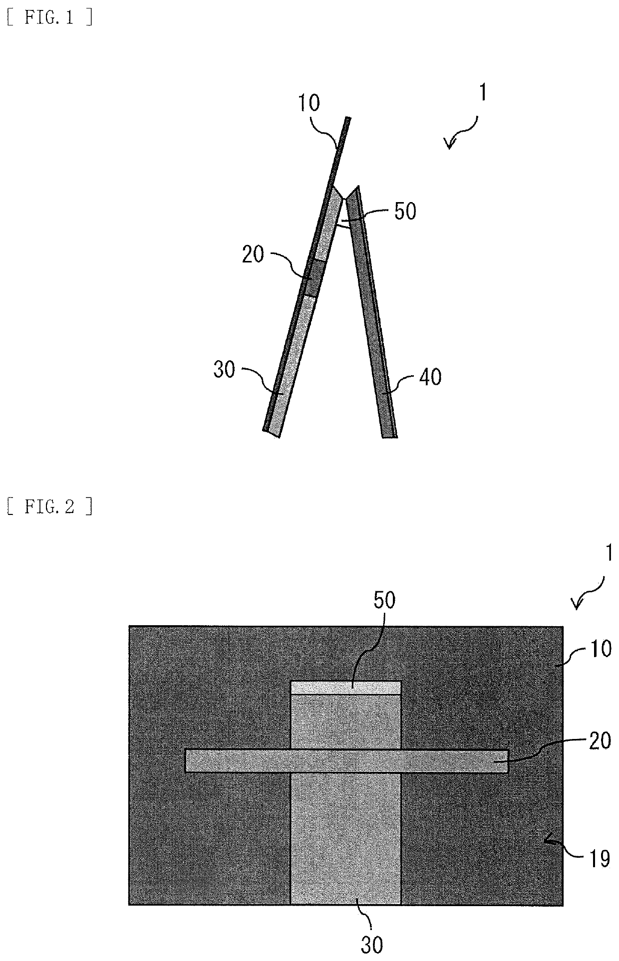
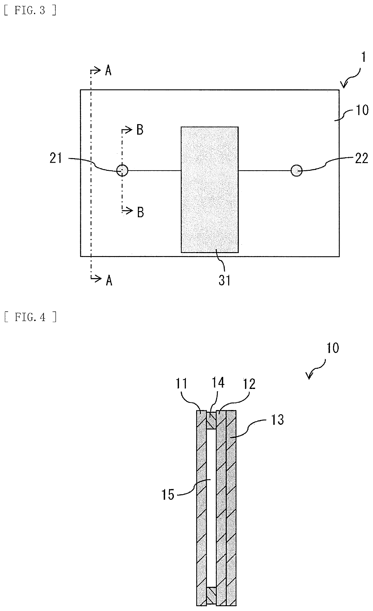
[0061]A flat panel speaker 1 according to a first embodiment of the disclosure is described. FIG. 1 illustrates a side-face configuration example of the flat panel speaker 1 according to the present embodiment. FIG. 2 illustrates a rear-face configuration example of the flat panel speaker 1 in FIG. 1. The flat panel speaker 1 also serves as a display unit that displays an image. In other words, it may be said that the display unit includes the flat panel speaker 1 built therein, and is configured to be able to output sound from a display surface that displays an image.
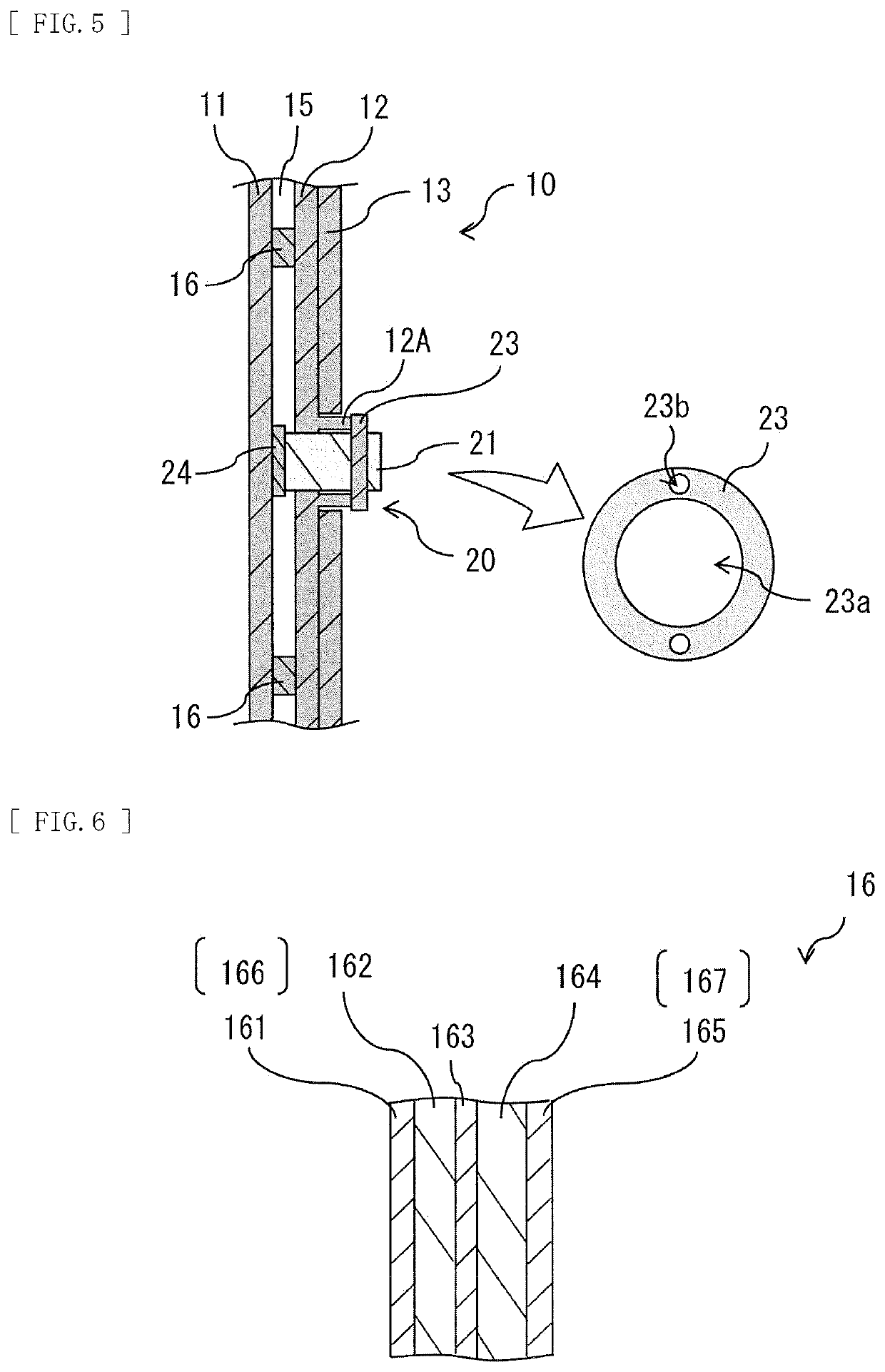
[0062]The flat panel speaker 1 includes, for example, a panel section 10 serving as a vibration plate, and a vibration section 20 disposed on a back surface of the panel section 10 and causing the panel section 10 to vibrate. The flat panel speaker 1 further includes, for example, a signal processor 30 that controls the vibration section 20, and a support section 40 that supports the p...
modification example
2. Modification Example of First Embodiment
[0102]In the foregoing embodiment, for example, the support section 40 and the rotation section 50 may be omitted as illustrated in FIG. 22 and FIG. 23. In this case however, preferably, the back chassis 19 is provided with a recess 32 to be used for hanging the flat panel speaker 1 on a hook provided on a wall, etc. It is to be noted that in a case where a flat panel speaker 2 is placed on a table top stand, the above-described recess 32 may be absent.
second embodiment
3. Second Embodiment
[Configuration]
[0103]Next, a flat panel speaker 2 according to a second embodiment of the disclosure is described. FIG. 24 illustrates a side-face configuration example of the flat panel speaker 2 according to the present embodiment. FIG. 25 illustrates a rear-face configuration example of the flat panel speaker 2 in FIG. 24. The flat panel speaker 2 also serves as a display unit that displays an image. In other words, it may be said that the display unit includes the flat panel speaker 2 built therein, and is configured to be able to output sound from a display surface that displays an image.
[0104]The flat panel speaker 2 includes, for example, a panel section 60 serving as a vibration plate, and a vibration section 70 disposed on a back surface of the panel section 60 and causing the panel section 60 to vibrate. The flat panel speaker 2 further includes, for example, a support section 80 in which a signal processing circuit 81 that controls the vibration sectio...
PUM
| Property | Measurement | Unit |
|---|---|---|
| audio frequencies | aaaaa | aaaaa |
| frequency | aaaaa | aaaaa |
| audio frequencies | aaaaa | aaaaa |
Abstract
Description
Claims
Application Information
 - R&D
- Intellectual Property
- Life Sciences
- Materials
- Tech Scout
- Unparalleled Data Quality
- Higher Quality Content
- 60% Fewer Hallucinations
Browse by: Latest US Patents, China's latest patents, Technical Efficacy Thesaurus, Application Domain, Technology Topic, Popular Technical Reports.
© 2025 PatSnap. All rights reserved.Legal|Privacy policy|Modern Slavery Act Transparency Statement|Sitemap|About US| Contact US: help@patsnap.com


