Conductive noise suppressor, power converter, and motor device
a technology of conductive noise and suppressor, which is applied in the direction of ac-ac conversion, power conversion systems, control systems, etc., can solve the problems that the conductive common mode noise of a high frequency component might rather be deteriorated, and the power converter generates conductive noise, so as to suppress the worsening of noise
- Summary
- Abstract
- Description
- Claims
- Application Information
AI Technical Summary
Benefits of technology
Problems solved by technology
Method used
Image
Examples
first embodiment
Motor Device
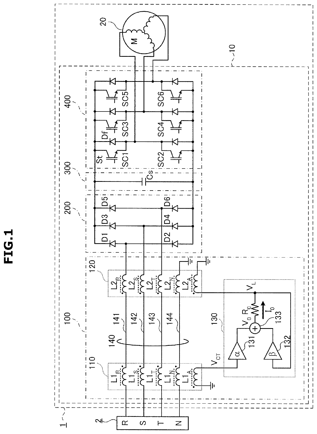
[0029]FIG. 1 illustrates a motor device in accordance with a first embodiment of the disclosure.
[0030]A motor device 1 may be connected to a three-phase four-wire alternate current (AC) power supply 2 having a neutral phase (N phase).
[0031]Here, first to third phases are denoted by R phase, S phase, and T phase. Power lines for supplying R, S, T, and N phase power from the AC power supply 2 are denoted as an R phase power line 141, an S phase power line 142, a T phase power line 143, and an N phase power line 144. Without distinguishing the phases, they may be collectively denoted as a power line 140. Even when coils in the first coil part 110 and the second coil part 120 as will be mentioned later are inserted in series, the name power line 140 remains the same.
[0032]A motor device 1 includes a power converter 10 and a motor 20.
[0033]The motor 20 may be driven by three-phase AC current supplied by the inverter 400 of the power converter 10 as will be described below.
[00...
second embodiment
A Second Embodiment
[0150]The motor device 1 of the first embodiment as shown in FIG. 1 receives an AC current from the AC power supply 2 of a three-phase four-wire system. However, motor device 1 of the second embodiment receives an AC current from the AC power supply 2 of a three-phase three-wire system.
[0151]FIG. 4 illustrates a motor device1 in accordance with a second embodiment of the disclosure.
[0152]As shown in FIG. 4, the motor device 1 of the second embodiment does not include the N-phase power supply line 144 for the motor device 1 of FIG. 1. That is, the second embodiment or the motor device 1 include a three-phase three-wire AC power supply 2.
[0153]The remaining components of the motor device 1 are the same as those in the motor device 1 according to the first embodiment of the disclosure as shown in FIG. 1, and given the same reference numerals as those of the motor device 1, so the description thereof will be omitted.
[0154]Even in the motor device 1 using the three-pha...
third embodiment
A Third Embodiment
[0155]The motor device 1 according to the first embodiment of the disclosure and the motor device 1 according to the second embodiment of the disclosure receive an AC current from the three phase AC power supply 2.
[0156]FIG. 5 illustrates a motor device in accordance with a third embodiment of the disclosure.
[0157]As shown in FIG. 5, the motor device 1 according to the third embodiment has an X phase and a Y phase instead of the R phase and the S phase of the motor device 1 as shown in FIG. 1, and does not have the T phase and the N phase. The rectifier 200 includes four rectifying diodes D1 to D4. That is, the AC power supply 2 supplies single-phase two-wire power.
[0158]The remaining components of the motor device 1 are the same as those of the motor device 1 according to the first embodiment as shown in FIG. 1. Accordingly, the same reference numerals are given to the components and the description thereof will be omitted. In addition, R is substituted with X, an...
PUM
 Abstract
Description
Claims
Application Information
 - R&D
- Intellectual Property
- Life Sciences
- Materials
- Tech Scout
- Unparalleled Data Quality
- Higher Quality Content
- 60% Fewer Hallucinations
Browse by: Latest US Patents, China's latest patents, Technical Efficacy Thesaurus, Application Domain, Technology Topic, Popular Technical Reports.
© 2025 PatSnap. All rights reserved.Legal|Privacy policy|Modern Slavery Act Transparency Statement|Sitemap|About US| Contact US: help@patsnap.com


