
Method for resisting dynamic load in high temperature pipeline

a dynamic load and pipeline technology, applied in the field of dynamic load analysis technology, can solve the problems of not being able to meet the requirements of both temperature stress and seismic stress at the same time, the cost of a snubber is very high, and the effect of reducing the use of a snubber

Active Publication Date: 2021-08-10
CHINA NUCLEAR POWER ENG CO LTD
View PDF21 Cites 0 Cited by
  • Summary
  • Abstract
  • Description
  • Claims
  • Application Information

AI Technical Summary

Benefits of technology

This approach allows for a cost-effective pipeline design that satisfies both temperature and seismic stress requirements without the need for extensive snubber use, reducing construction and maintenance costs while ensuring effective load resistance.

Problems solved by technology

However, it is not easy to satisfy a requirement for both the temperature stress and the seismic stress simultaneously.
A cost of a snubber is very high, and is far higher than that of a rigid bracket.
Using snubbers in a large quantity will not only increase the cost of components of a pipeline system but also greatly increase an operation cost of the pipeline system, because the snubber itself may cease to be effective, for example, it is prescribed in nuclear power plants that 10% of the snubbers must be checked and repaired every year.
This procedure reduces economic performance of the pipeline system.

Method used


Image

  • Method for resisting dynamic load in high temperature pipeline
  • Method for resisting dynamic load in high temperature pipeline
  • Method for resisting dynamic load in high temperature pipeline

Examples


Embodiment Construction

[0023]The present disclosure will be described in detail below in connection with accompanying drawings and embodiments.

[0024]A technical principle adopted in the present disclosure is that a temperature stress is generated by a temperature deformation being subject to a constraint, while the temperature deformation necessarily has a definite direction. In arranging a pipeline, as long as the constraint is released in a temperature deformation direction, a large temperature stress will not be generated. In principle, application of a constraint in a direction perpendicular to the temperature deformation will not have a significant influence on the temperature stress. Therefore, it is necessary to find the temperature deformation displacement under a specific pipeline arrangement, and such deformation displacement ought to be a deformation displacement of each point having a definite direction and a definite magnitude. After that, where the maximum internal force or the maximum inter...


PUM


Abstract

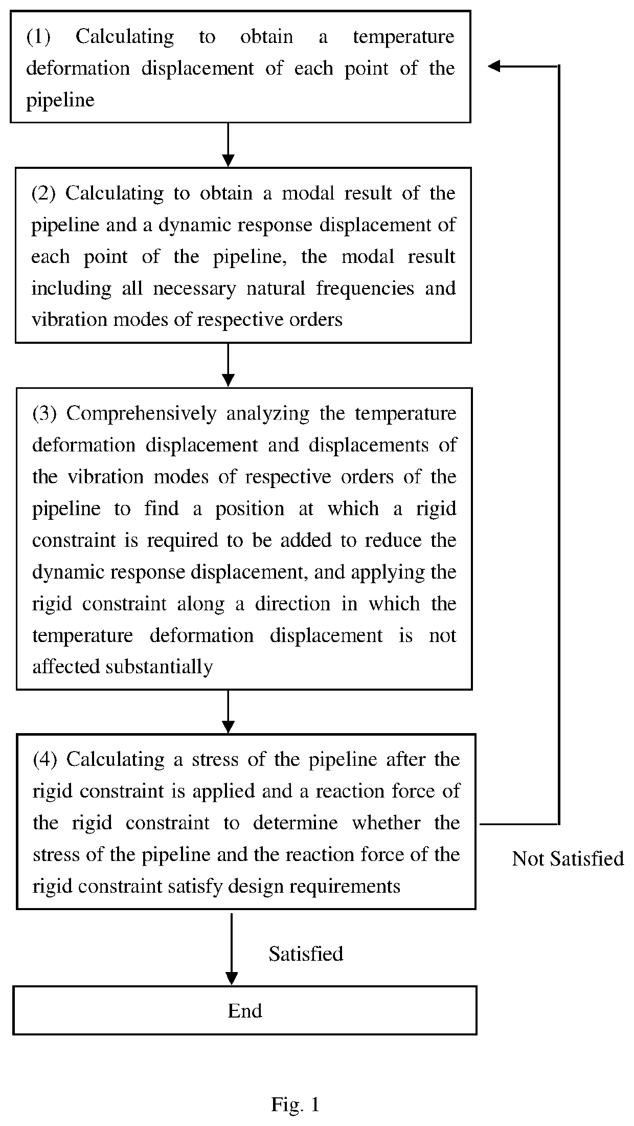
Disclosed is a design method for resisting a dynamic load in a high temperature pipeline. The method includes the following steps: a first calculation step, calculating to obtain a temperature deformation displacement of each point of the pipeline; a second calculation step, calculating to obtain a modal result of the pipeline and a dynamic response displacement of each point of the pipeline; a comprehensive analysis step, comprehensively analyzing the temperature deformation displacement and displacements of the vibration modes of respective orders of the pipeline to find a position at which a rigid constraint is required to be added, and applying the rigid constraint along a direction in which the temperature deformation displacement is not affected substantially; and a determination step, calculating a stress of the pipeline and a reaction force of the rigid constraint to determine whether the stress and the reaction force meet design requirements.

Description

CROSS-REFERENCE TO RELATED APPLICATION[0001]This application claims priority to Chinese Patent Application No. 201710834417.1 filed Sep. 15, 2017, the disclosure of which is hereby incorporated in its entirety by reference.BACKGROUND OF THE INVENTIONField of the Invention[0002]The present disclosure relates to a dynamic load analysis technology, and particularly, relates to a design method for resisting a dynamic load in a high temperature pipeline.Description of Related Art[0003]A variety of loads need to be considered in pipeline mechanics calculation in the industrial community, especially for nuclear power plants, all temperature operating conditions and influence of dynamic loads such as earthquake etc. should be considered. It is well known that a temperature load and a seismic load of a pipeline are a pair of contradictions. A condition for satisfying the temperature load is to increase a flexibility of a pipeline system (or to reduce a rigidity of a pipeline system). On the ...

Claims


Application Information

Patent Timeline
Patent Type & Authority Patents(United States)
IPC IPC(8): G06F30/17G06F30/20G06F111/04G06F111/10G06F113/14G06F119/08
CPCG06F30/17G06F30/20G06F2111/04G06F2111/10G06F2113/14G06F2119/08Y02E60/00Y04S40/20G06F2119/06G06F30/18G06F2119/14
Inventor LIU, SHUBINWU, MINGZHANG, SHUANGWANGCHEN, LIWANG, YUANZHUSHENG, FENG
Owner CHINA NUCLEAR POWER ENG CO LTD
Learn More