
Bearing for a screw rotor of a screw compressor

a screw compressor and bearing technology, applied in the direction of machines/engines, rotary/oscillating piston pump components, liquid fuel engines, etc., can solve the problems of increasing the load applied to the bearings, high cost, etc., and achieves the effect of increasing the size of the screw compressor, increasing the distance, and increasing the load applied

Active Publication Date: 2021-08-10
DAIKIN IND LTD
View PDF9 Cites 0 Cited by
  • Summary
  • Abstract
  • Description
  • Claims
  • Application Information

AI Technical Summary

Benefits of technology

The patent text describes a way to increase the size of a compressor by using a larger screw rotor and drive shaft. This leads to larger bearings and increased load on them, which can result in higher costs. The technical effect of the patent is to provide a solution to increase the compressor size without adding too much to the cost.

Problems solved by technology

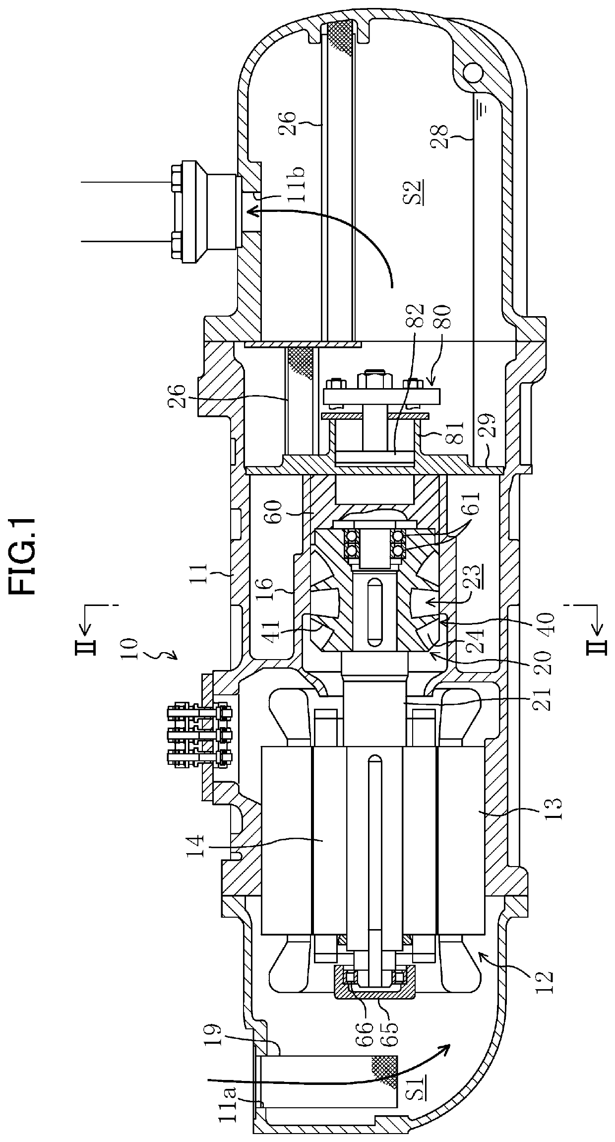
As a result, the load applied to the bearings (61, 66) increases, and the cost tends to be high.
However, when such a material is used, with an increase in the length of the drive shaft (21) due to the increase in size of the compressor, the cost is increased.
In the prior art of FIGS. 12B and 13, for example, when the screw compressor is increased in size, the cost is increased due to the increase in the length of the drive shaft (121) whose material is expensive.

Method used


Image

  • Bearing for a screw rotor of a screw compressor
  • Bearing for a screw rotor of a screw compressor
  • Bearing for a screw rotor of a screw compressor

Examples


first embodiment

—Variation of

[0067]The above embodiment adopts the assembling method by which the inner ring of the high-pressure-side bearing (61) is fixed to the shaft (62a) of the high-pressure-side bearing holder (60). Alternatively, another assembling method by which the outer ring of the high-pressure-side bearing (61) is fixed to the wall surface defining the bearing hole (42) of the screw rotor (40) may be adopted.

[0068]In the above embodiment, the high-pressure-side bearing holder (60) is comprised of the bearing holder body (62b) and the shaft (62a) that are integral with each other. Alternatively, as shown in FIG. 10, the high-pressure-side bearing holder (60) may be formed by fixing the bearing holder main body (62b) and the shaft (62a), which are separate members, to each other.

second embodiment

[0069]A second embodiment of the present invention will be described.

[0070]In the second embodiment shown in FIG. 11, a bearing holder body (63a) of the high-pressure-side bearing holder (60) is provided with a boss (63b) projecting toward the screw rotor (40), and the boss (63b) is provided with a bearing hole (63c). The screw rotor (40) is provided with an inner hole (43) which has a larger diameter than the boss (63b) of the high-pressure-side bearing holder (60) and in which the boss (63b) is received. The drive shaft (21) has a shaft end (21a) inserted into the boss (63b). The high-pressure-side bearing (61) is mounted between the shaft end (21a) of the drive shaft (21) and the wall surface defining the bearing hole (63c) of the boss (63b).

[0071]With the above structure, a portion of the high-pressure-side bearing (61) is disposed inside the screw rotor (40). However, in the second embodiment, the whole of the high-pressure-side bearing (61) may be disposed inside the screw rot...


PUM


Abstract

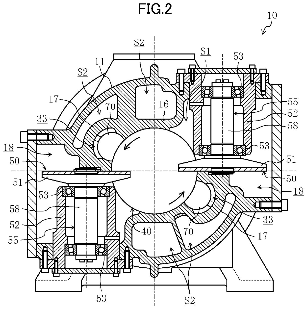
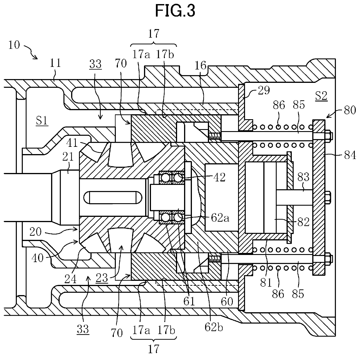
A screw compressor includes a casing, a motor provided in the casing, a screw rotor inserted into a cylinder in the casing, a bearing holder, a drive shaft, a first bearing, and a second bearing. The cylinder is formed on a lateral side of the motor. The bearing holder is disposed on an opposite side of the screw rotor from the motor and adjacent to the screw rotor. The drive shaft is connected to the motor and the screw rotor. The first bearing is disposed adjacent to the screw rotor. The second bearing is disposed adjacent to the motor in an axial direction of the drive shaft. At least a portion of the first bearing is disposed inside the screw rotor.

Description

CROSS-REFERENCE TO RELATED APPLICATIONS[0001]This U.S. National stage application claims priority under 35 U.S.C. § 119(a) to Japanese Patent Application No. 2017-028579, filed in Japan on Feb. 20, 2017, the entire contents of which are hereby incorporated herein by reference.TECHNICAL FIELD[0002]The present invention relates to a screw compressor, and in particular, to a bearing structure of a drive shaft.BACKGROUND ART[0003]Screw compressors including a compression mechanism having a screw rotor and a gate rotor have been known.[0004]Japanese Unexamined Patent Publication No. 2015-038334 discloses a screw compressor of this type. In this screw compressor, as shown in FIG. 13, bearings (161, 166) are arranged on a drive shaft (121) at each side of a screw rotor (140), so that the bearings (161, 166) receive a force generated by compression. A bearing holder (160) is disposed adjacent to the screw rotor (140).SUMMARY[0005]To increase the size of the compressor, the screw rotor (40) ...

Claims


Application Information

Patent Timeline
Patent Type & Authority Patents(United States)
IPC IPC(8): F03C2/00F03C4/00F04C18/00F04C2/00F04C18/52F04C18/16F04C28/12
CPCF04C18/52F04C18/16F04C28/12F04C2240/52F04C2240/605F04C29/00F01C21/02F04C2240/56F01C21/08F04C2240/20
Inventor SHIKANO, SHIGEHARUMIYAMURA, HARUNORIMORI, KAZUKI
Owner DAIKIN IND LTD
Learn More