Method of manufacturing decorative surfaces

a technology of decorative surfaces and manufacturing methods, applied in the field of decorative panels, can solve the problems of clogging of the nozzle in the inkjet print head unit, affecting the quality of the inkjet print, so as to delay the production time of rendering wood patterns

Active Publication Date: 2021-08-10
AGFA NV
View PDF15 Cites 0 Cited by
  • Summary
  • Abstract
  • Description
  • Claims
  • Application Information

AI Technical Summary

Benefits of technology

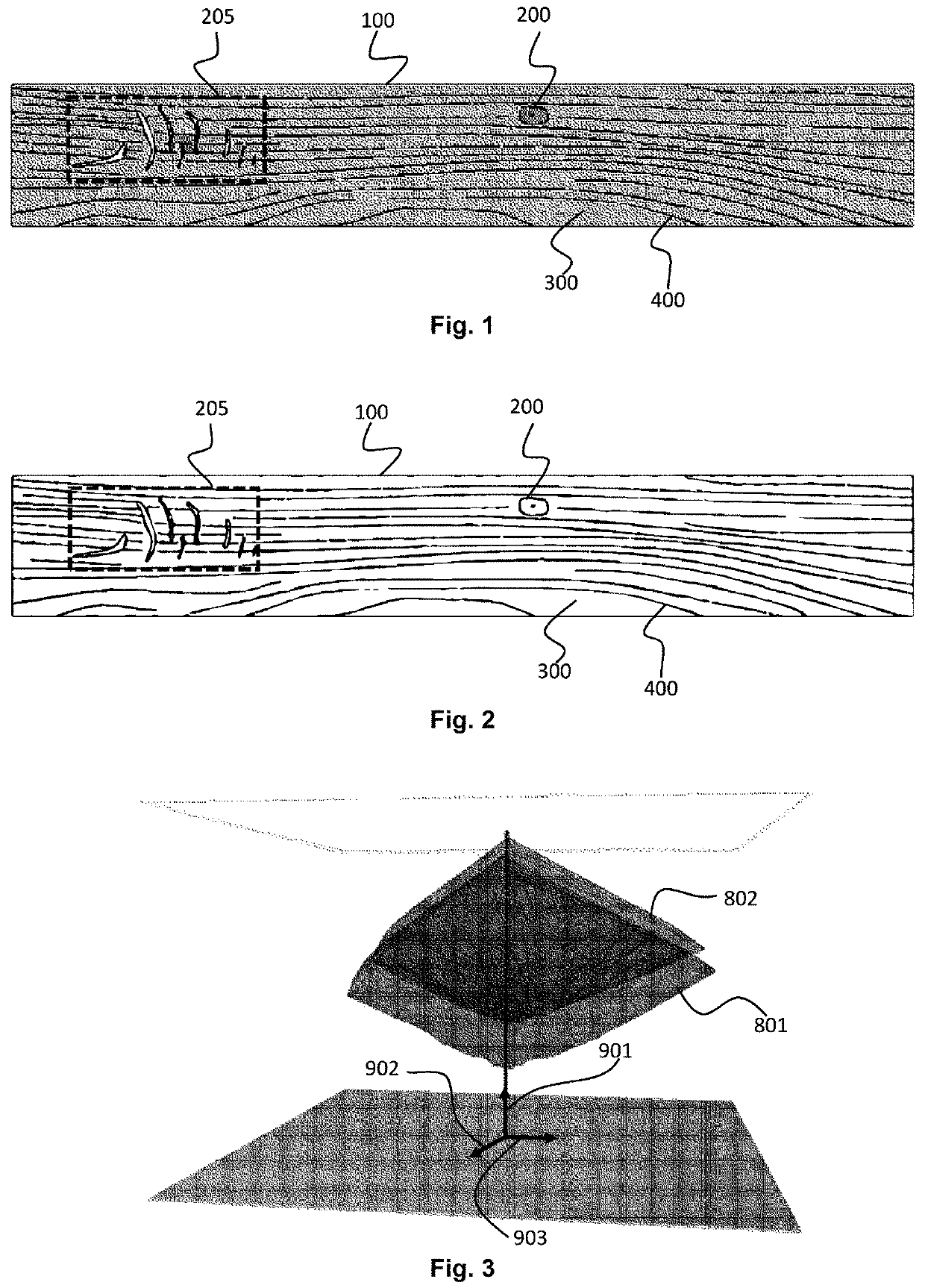
[0022]The advantage by jetting droplets, based on the selection mask (M1 . . . M, 1 . . . N), to prevent that inactive nozzles dry out, is that the background color, also called the wood tone, remains the same; which is not the case in the spitting method disclosed in WO2016 / 113190 (AGFA GRAPHICS NV). The one or more wood nerves; one or more wood pores and / or one or more wood imperfections represented by said selection mask (M1 . . . M, 1 . . . N), if printed on top of wood nerves, wood pores and / or wood imperfections from the wood pattern, becomes after rendering slightly darker by luminance change or changes after rendering slightly in chroma or hue but it is found that this is not noticeable in a manufactured decorative surface, such as laminate, because the background color of the wood pattern (W1 . . . M, 1 . . . N) remains still the same after heat pressing. The present invention gives also the small advantage to have slightly differences between copies of the same rendered wood pattern (W1 . . . M, 1 . . . N), which minimized patterning in an assembled floor of decorative surfaces, manufactured as in the present invention.
[0026]The present invention shortens the inactivity of a nozzle to prevent that the nozzle is clogged and / or dried out. This enhances the reliability of the manufacturing of decorative surfaces comprising a wood pattern. The time of inactivity may be calculated out the wood pattern whereby each pixel is assigned to one or more nozzles of the inkjet print head unit. The non-assigned nozzles are nozzles with a larger inactivity, which may be determined by the present invention. In a preferred embodiment the determining step comprises:
[0029]By jetting these extra droplets while rendering the wood pattern for preventing the clogging, the full area of the substrate can be used for manufacturing decorative surfaces, such as laminate. Also, by jetting these extra droplets while rendering the wood pattern for preventing the clogging, makes that manufacturing of the decorative surface is not disturbed by stopping the process for cleaning nozzles from the inkjet print head unit. The advantage is that these extra droplets becomes not noticeable in manufactured decorative surfaces, which comprises the wood pattern rendered as the present invention.

Problems solved by technology

In an industrial environment for the manufacturing of decorative panels, a nozzle in an inkjet print head unit may be clogged after a time of printing but also after a time of non-printing.
Dust (e.g. from substrate) in the environment of the inkjet print head unit are detrimental for the operability of nozzles in the inkjet print head unit.
Also, the drying of rendered wood patterns may result in emissions from the jetted droplets, which clogs the ink in the nozzles.
The radiation of drying units for drying a rendered wood pattern and high temperatures in the environment of the inkjet print head unit may also result in clogging of a nozzle in the inkjet print head unit.
In addition, the movement of substrate and inkjet print head unit may result in the drying out of the nozzle so ink gets clogged in the nozzle.
Also mist from jetted droplets results in clogged nozzles.
This heat also dries the nozzle so ink gets clogged in the nozzle.
A clogged nozzle results in a wrong placing of a droplet on the substrate by a disturbed trajectory of the droplet or results a failure of jetting droplets from said clogged nozzle.
When such nozzle fails or jets on a wrong place, this result in a bad rendered wood pattern with density shortage and / or a disturbance in the defective wood pattern for example a non-jetted line.
To keep nozzles not get dried out, spitting when no wood pattern is jetted, should be a solution but this put the production timing of decorative panels in danger because the time of keeping nozzles alive downsizes the production capacity due to longer production timings, which is an economic disadvantage.

Method used


Image

  • Method of manufacturing decorative surfaces
  • Method of manufacturing decorative surfaces

Examples


Embodiment Construction

[0053]The substrate may be a paper and the other substrate a wood-based layer for decorative laminates, as decorative surfaces, wherein the manufacturing comprises an additional step before and / or after rendering:[0054]impregnating the paper by a thermosetting resin.

[0055]Thermosetting resin is preferably selected from the group consisting of melamine-formaldehyde based resins, ureum-formaldehyde based resins and phenol-formaldehyde based resins.

[0056]The substrate may comprise an inkjet-receiving layer, which preferably contains an inorganic pigment P and a polymeric binder B; and more preferably, wherein the pigment P is selected from the group consisting of alumina hydrates, aluminum oxides, aluminum hydroxides, aluminum silicates, and silicas. The wood pattern is than rendered on the inkjet-receiving layer. This inkjet-receiving layer is to prevent that the color strength of the wood pattern is not reduced due to the absorbing of the jetted inks in the substrate. The inkjet-rece...


PUM

PropertyMeasurementUnit
temperatureaaaaaaaaaa
total volumeaaaaaaaaaa

Abstract

A method of manufacturing decorative panels includes selecting a paper with a paper weight between 50 g / m2 and 130 g / m2 and a porosity according to Gurley's method between 8 and 20 seconds; selecting a wood pattern; generating a selection mask representing one or more wood nerves; one or more wood pores, and / or one or more wood imperfections from the wood pattern, by image analyzing the wood pattern; and supplying the wood pattern and the selection mask to an inkjet print head unit for forming a decorative layer. The inkjet print head unit includes a plurality of nozzles and the method further includes determining a set of nozzles from the plurality of nozzles based on an inactivity of a nozzle by calculating an inactivity-duration for the nozzles and by comparing the calculated inactivity-duration to a threshold value; wherein a part of the selection mask is formed with the determined set of nozzles.

Description

CROSS REFERENCE TO RELATED APPLICATIONS[0001]This application is a 371 National Stage Application of PCT / EP2018 / 076623, filed Oct. 1, 2018. This application claims the benefit of European Application No. 17194346.7, filed Oct. 2, 2017, which is incorporated by reference herein in its entirety.BACKGROUND OF THE INVENTION1. Field of the Invention[0002]The present invention to a method for manufacturing decorative panels, which comprises rendering wood pattern by inkjet technology to have a decorative surface that looks and feels as wood.2. Description of the Related Art[0003]Wood patterns are traditional printed by conventional printing technology such as offset or rotogravure printing in resolution above 1800 DPI (dots-per-inch) with several colored inks.[0004]More and more, instead of analogue printing techniques, is digital printing technology tried for rendering the wood patterns by marking devices for manufacturing wood simulated decorative surfaces. The advantages of digital pri...

Claims


Application Information

Patent Timeline
Patent Type & Authority Patents(United States)
IPC IPC(8): B44C5/04B41M5/00B41J2/01B41J11/00E04F15/02
CPCB41M5/0047B44C5/04B32B2260/028B32B2260/046B32B2307/554B32B2607/00B41J2/01B41J11/002E04F15/02B41J2/16526B41J11/0015B41J2002/16529B44F9/02B41J11/00214B41J11/00216B41J11/0021B41J3/407
Inventor VANHOOYDONCK, RUDI
Owner AGFA NV
Why Eureka
Try Eureka