
System and method of reciprocating piston engine, multi-fuel piston engine

a multi-fuel, reciprocating technology, applied in the field of reciprocating piston engines, can solve the problems of damaging the piston knocking phenomenon of most types of fuel we are using today, and none of the existing piston engines would work properly

Active Publication Date: 2021-08-03
CANADAVFD CORP LTD
View PDF3 Cites 1 Cited by
  • Summary
  • Abstract
  • Description
  • Claims
  • Application Information

AI Technical Summary

Benefits of technology

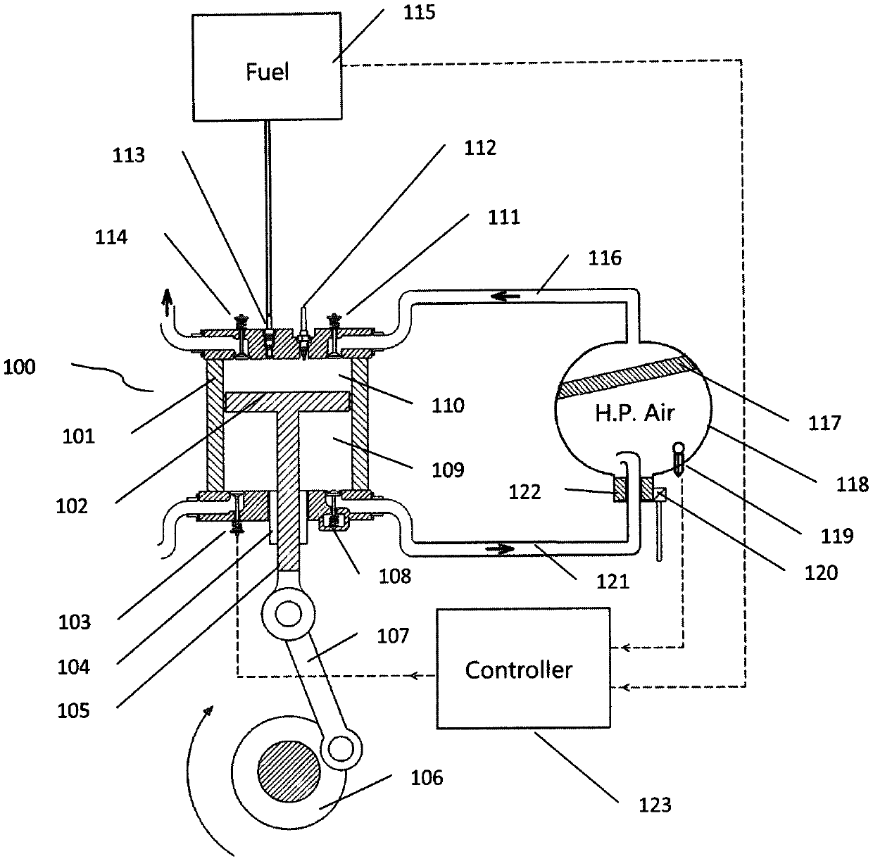
The present invention provides a piston engine that has improved combustion efficiency and output torque compared to traditional piston engines. The invention allows for the movement of the peak pressure of combustion to a specific position, which results in increased tangential force on the crankshaft. Additionally, the piston engine has a significantly reduced clearance volume, allowing for the use of different types of fuel. The air compression chamber can also recover and store the kinetic energy from the moving crankshaft to further improve fuel efficiency. The engine controller controls the intake valves to compress the fresh air and controls the position of the peak pressure of combustion to optimize engine performance.

Problems solved by technology

If the compression ratio is increased to 50:1, none of the existing piston engines would work properly.
In other words, none of the existing piston engines would work properly if the clearance volume Vc is less than 1 / 50 Vd.
If the clearance volume is less than 1 / 50 Vd, the damaging piston knocking phenomena occurs for most types of fuel we are using today, such as gasoline, diesel, ethanol, or vegetable oils.
A piston engine can only use one type of fuel efficiently, for example, a gasoline engine which burns gasoline cannot achieve its effect by burning ethanol.

Method used


Image

  • System and method of reciprocating piston engine, multi-fuel piston engine
  • System and method of reciprocating piston engine, multi-fuel piston engine
  • System and method of reciprocating piston engine, multi-fuel piston engine

Examples


Embodiment Construction

[0118]It is to be understood that the disclosure is not limited in its application to the details of the embodiments as set forth in the following description. The invention is capable of other embodiments and of being practiced or of being carried out in various ways.

[0119]Furthermore, it is to be understood that the terminology used herein is for the purpose of description and should not be regarded as limiting. Contrary to the use of the term “consisting”, the use of the terms “including”, “containing”, “comprising”, or “having” and variations thereof is meant to encompass the items listed thereafter and equivalents thereof as well as additional items. The use of the term “a” or “an” is meant to encompass “one or more”. Any numerical range recited herein is intended to include all values from the lower value to the upper value of that range.

[0120]The term “clearance volume” used herein does not include the “valve sets crevice volumes, spark plug crevice volume, piston ring crevic...


PUM


Abstract

The present disclosure relates to piston engine systems which are no longer restricted by their compression ratios. Rather, a mixture of fuel and pre-compressed air is used to complete the combustion. The pressure of the compressed air is independently controlled. As a result, the clearance volume can be reduced to less than 1 / 50 or to zero, and the piston engine systems can be used with different types of fuels, for example, gasoline, diesel, ethanol, or vegetable oils.

Description

FIELD OF THE INVENTION[0001]The present disclosure relates to piston engine. More specifically, the present disclosure relates to reciprocating piston engine and multi-fuel piston engine systems which are not restricted by their compression ratio.BACKGROUND OF THE INVENTION[0002]Each type of fuel has its own characteristics; and as such, requires different combustion conditions.[0003]Generally speaking, in a piston combustion engine, compression ratio is the ratio of the maximum to minimum volume in the cylinder, in other words, it is the ratio of the volume of the combustion chamber when the piston is at the bottom dead center (BDC) (at maximum volume) and the volume of the combustion chamber when the piston is at the top dead center (TDC) (at minimum volume). The volume of the combustion chamber when the piston is at the top dead center TDC is often referred as clearance volume Vc. The volume of the combustion chamber the piston travelled from BDC to TDC is often referred as displ...

Claims


Application Information

Patent Timeline
Patent Type & Authority Patents(United States)
IPC IPC(8): F02B75/28F02B75/16F01M13/04F02B33/30B60K15/03B60K13/00F02D13/02F02B33/04F02B21/00
CPCF02B75/28B60K13/00B60K15/03006F01M13/04F02B21/00F02B33/04F02B33/30F02B75/16F02D13/0223B60K2015/0321B60K2015/03243F02D2200/0611F01B7/14F02D13/0276F02D15/00F02D19/0655Y02T10/12Y02T10/30Y02T10/40
Inventor YUAN, DEFANG
Owner CANADAVFD CORP LTD
Learn More