
Interbody implant with concave profiled nose

a technology of implanted implants and noses, which is applied in the field of spinal fusion implants, can solve the problems of high stress on the vertebrae, and achieve the effect of facilitating implant insertion

Active Publication Date: 2021-07-13
ADVANCE RES SYST LLC
View PDF89 Cites 2 Cited by
  • Summary
  • Abstract
  • Description
  • Claims
  • Application Information

AI Technical Summary

Benefits of technology

[0006]Various embodiments of the disclosed cage-type interbody implant facilitates insertion of the implant at reduced forces relative to conventional cage-type interbody implants. The profile of a nose portion of the interbody implant provides a small cross-sectional area proximate the distal end of the nose portion that is readily inserted into gaps within the spine structure. The outer surface of the nose portion slopes more gradually at the distal locations of the nose portion than at the proximal or base portions of the nose. This enables the nose portion to become firmly yet easily aligned within the desired entry location between adjacent vertebrae before the maximum manipulation forces are applied for final insertion.
[0007]In some embodiments, the outer surface nose portion defines a cross-section perpendicular to a nose axis, the cross-sections defining rounded surfaces that substantially reduce or eliminate adjacent flats or straight portions and associated transition corners therebetween. Such flats and transition corners are common in conventional interbody implants, and can inhibit rotational manipulation of the implant during insertion. The rounded surfaces enable easier rotation and reduce the torsional manipulation forces of the interbody implant. The ease of rotation and reduced torsional manipulation forces are particularly notable during initial alignment and insertion of the nose portion, where only the distal portion of the nose having a small insertion cross-section is engaged with the targeted vertebrae.
[0008]In some embodiments, an implant system facilitates guidance of the interbody implant to the desired location in the spine and at a desired orientation. An inserter is configured for rotational and thrust manipulation, and may include a guide wire. The interbody implant may be configured to accommodate the guide wire, so that the implant system more accurately guides the interbody implant to the target location.
[0018]guiding the interbody implant for implantation at a target location; inserting the distal extremity of the nose portion of the interbody implant for implantation into the target location; and initially thrusting the mid portion of the nose portion for penetration of the target location, wherein the first cross-section being smaller than the second cross-section, the first acute angle being smaller than the second acute angle, and the shape of the first cross-section, combine to make the step of insertion and the step of initially thrusting the interbody implant easier than for state of the art fusion cages.

Problems solved by technology

Surgically implanting the interbody implants requires placement of the implant at desired locations and orientations, and in some procedures require substantial manipulation forces (thrust and torque) to accomplish insertion of the implant.
However, forces associated with the implantation of these interbody implants can be prohibitive, resulting in high stresses on the vertebrae during implantation.

Method used


Image

  • Interbody implant with concave profiled nose
  • Interbody implant with concave profiled nose
  • Interbody implant with concave profiled nose

Examples


Embodiment Construction

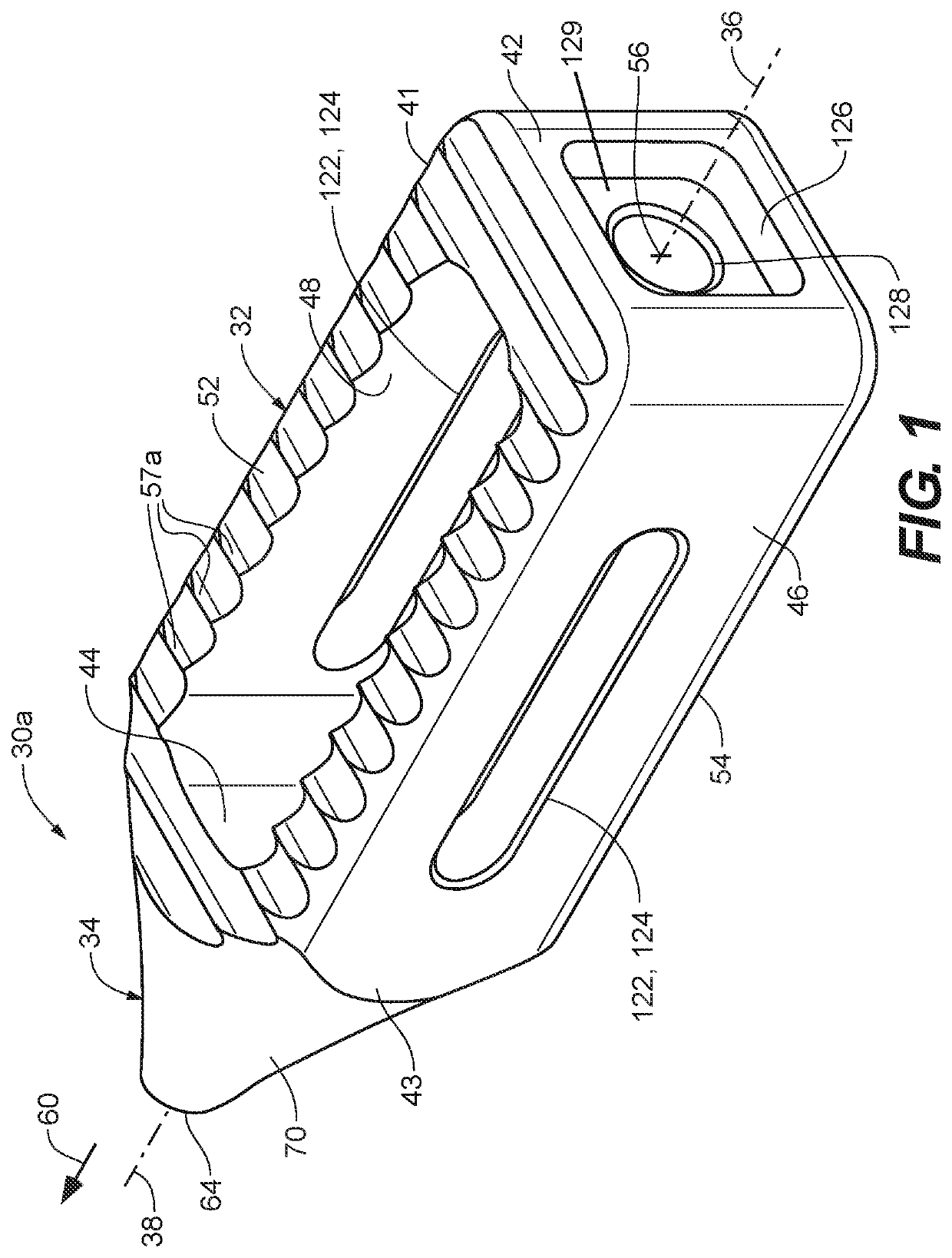
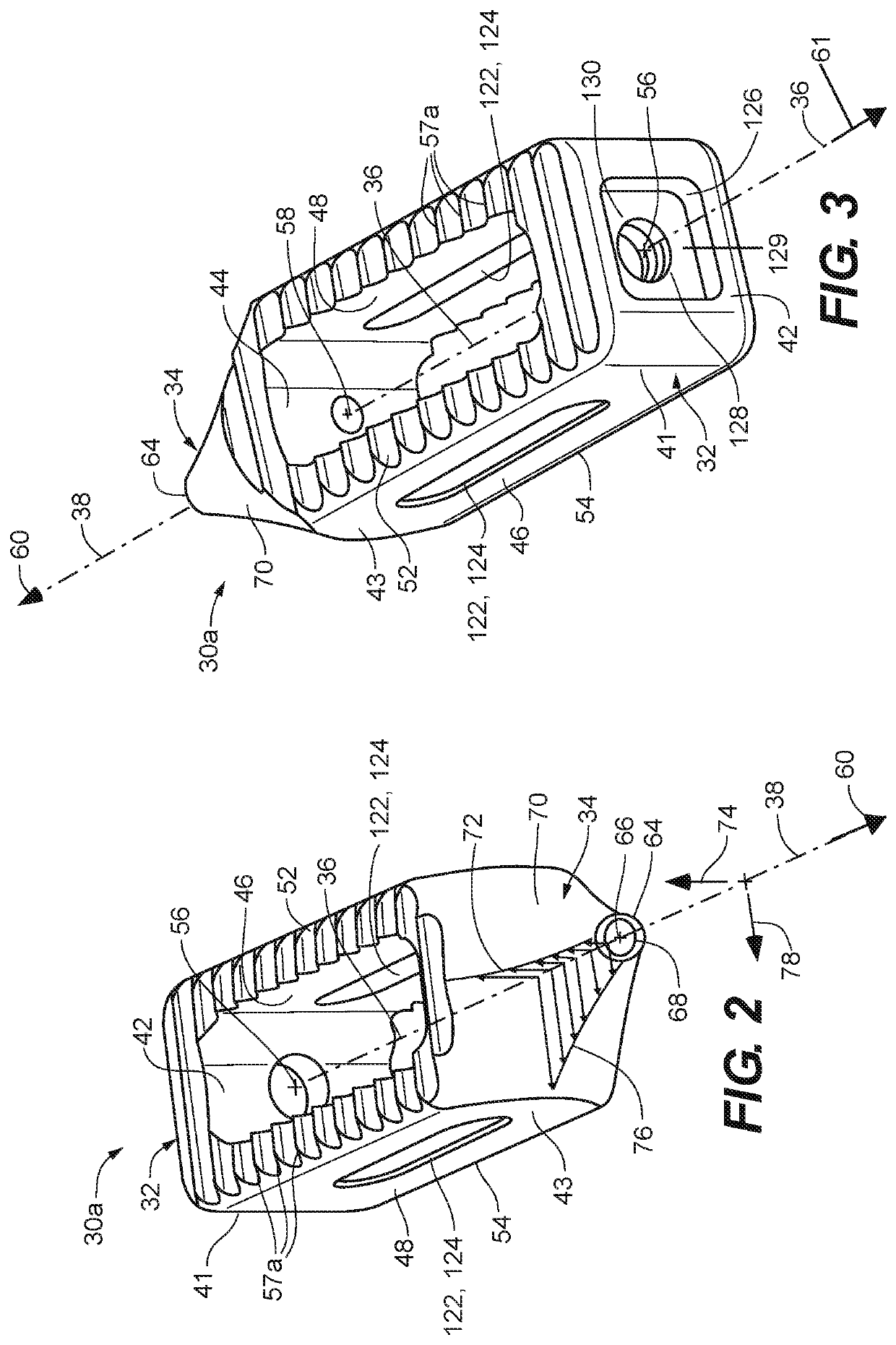
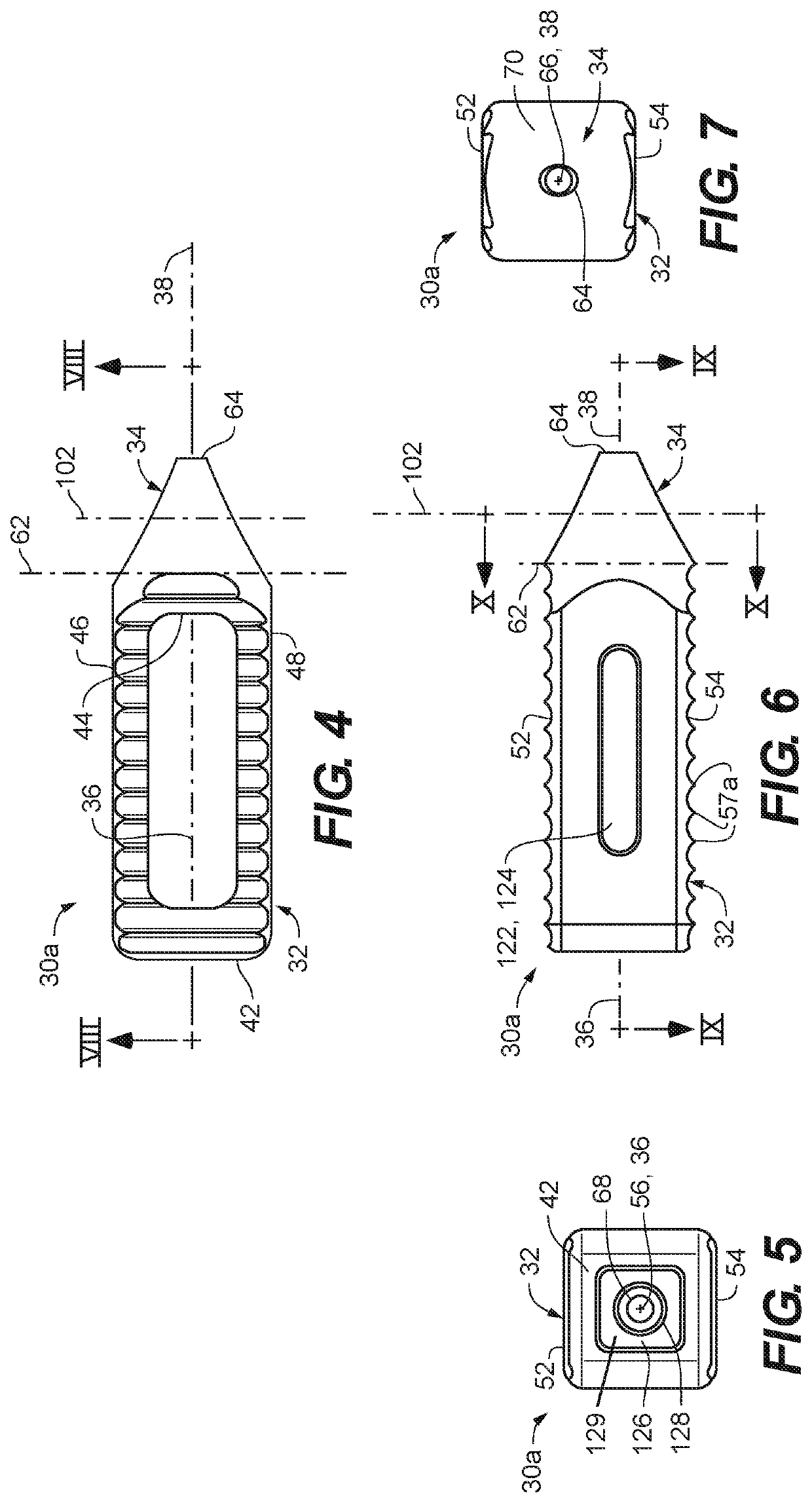
[0055]Referring to FIGS. 1 through 9, an interbody implant 30a is depicted according to an embodiment of the disclosure. The interbody implant 30a includes a cage portion 32 and a nose portion 34. The cage portion 32 includes a proximal portion 41 that may include a proximal wall 42 and a distal portion 43 that may include a distal wall 44. In the depicted embodiment, the proximal wall 42 and the distal wall 44 are separated by opposing side walls 46 and 48. The proximal wall 42, distal wall 44, and opposing side walls 46 and 48 cooperate to define opposed edge surfaces 52 and 54. The cage portion 32 defines a cage axis 36 that passes through a center 56 of the proximal wall 42 and a center 58 of the distal wall 44 (FIG. 3). In some embodiments, one or both of the opposed edge surfaces 52, 54 define a plurality of gripping facets 57a extending therefrom.

[0056]The nose portion 34 extends in a distal direction 60 from the distal portion 43, the nose portion 34 extending from a base pl...


PUM


Abstract

An interbody implant and inserter tool for spinal fusion. The interbody implant includes a cage portion and a nose portion. In some embodiments, an outer surface of the nose portion defines at least a first concave profile in a first direction, and may define a second concave profile in a second direction, the second direction being perpendicular to the first direction. The outer surface may also define an oblong cross-section normal to a nose axis. The oblong cross-section may be axisymmetric or continuously curved (or both) about the nose axis. The concave profile(s) enable easier initial insertion of for more precisely locating the interbody implant, so that the greater insertion forces required during implantation do not occur until the interbody implant is securely and accurately placed.

Description

RELATED APPLICATIONS[0001]The present application is a National Phase entry of PCT Application No. PCT / US2017 / 066641, filed Dec. 15, 2017, which claims the benefit of U.S. Provisional Patent Application No. 62 / 435,598, filed Dec. 16, 2016, and of U.S. Provisional Patent Application No. 62 / 524,079, filed Jun. 23, 2017, the disclosures of which are hereby incorporated by reference herein in their entirety.FIELD OF THE DISCLOSURE[0002]The disclosure relates generally to interbody implants for spinal fusion, and more specifically to spinal cage implants having insertion tips.BACKGROUND OF THE DISCLOSURE[0003]Interbody implants are utilized for spinal fusion (arthrodesis) to restrict movement between vertebrae. The implants support and immobilize adjacent vertebrae while new bone tissue grow between the vertebrae.[0004]Surgically implanting the interbody implants requires placement of the implant at desired locations and orientations, and in some procedures require substantial manipulati...

Claims


Application Information

Patent Timeline
Patent Type & Authority Patents(United States)
IPC IPC(8): A61F2/44A61F2/46A61F2/30
CPCA61F2/446A61F2/447A61F2/4611A61F2002/30113A61F2002/30116A61F2002/30125A61F2002/30593A61F2002/30904A61F2002/4627A61F2002/4629A61F2310/00023A61L27/06A61L2430/38A61F2/4455A61F2002/30126A61F2002/30273A61F2002/30616A61F2002/30772A61F2002/30261A61F2/4603
Inventor ABBASI, HAMID R.
Owner ADVANCE RES SYST LLC
Learn More