Fast response linear regulator with bias current control and overshoot and undershoot suppression

Active Publication Date: 2021-05-04
PIXART IMAGING INC
View PDF3 Cites 4 Cited by
  • Summary
  • Abstract
  • Description
  • Claims
  • Application Information

AI Technical Summary

Benefits of technology

The invention describes a device called an "undershoot suppressor" that reduces noise in a computer network. The device includes a capacitor and a resistor that work together to reduce noise in a specific signal. The result is a cleaner and more reliable signal for use in computer networks.

Problems solved by technology

The prior art circuit in FIG. 1 has a drawback that the bias current Ibb is fixed.

Method used


Image

  • Fast response linear regulator with bias current control and overshoot and undershoot suppression
  • Fast response linear regulator with bias current control and overshoot and undershoot suppression
  • Fast response linear regulator with bias current control and overshoot and undershoot suppression

Examples


Embodiment Construction

[0034]The drawings as referred to throughout the description of the present invention are for illustration only, to show the interrelations between the circuits and the signal waveforms, but not drawn according to actual scale.

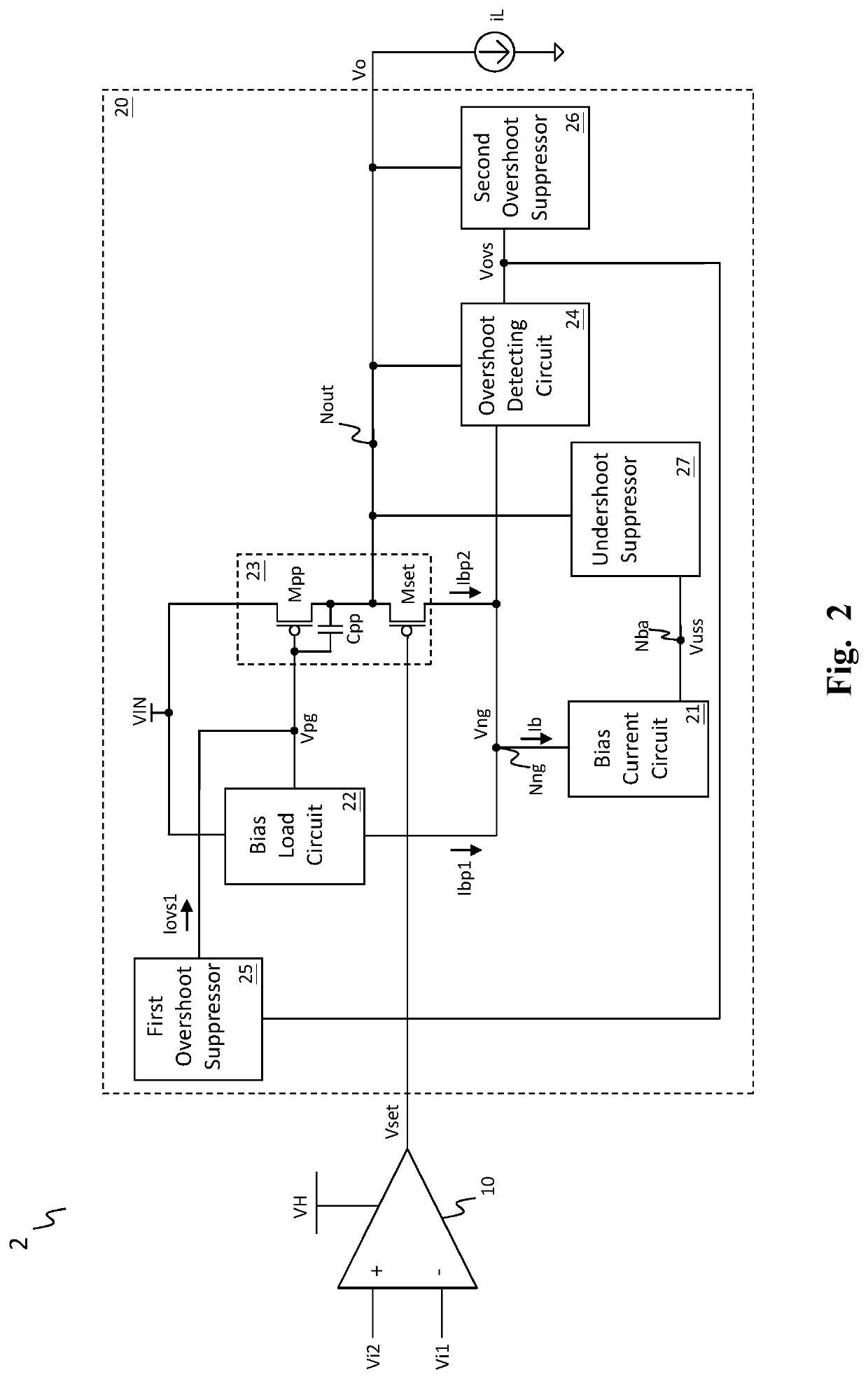
[0035]FIG. 2 shows a schematic diagram of an embodiment of the fast response amplifier circuit according to the present invention (fast response amplifier circuit 2). In one embodiment, as shown in FIG. 2, the fast response amplifier circuit 2 comprises a pre-stage circuit 10 and an output stage circuit 20. The pre-stage circuit 10 is configured to operably generate a control signal Vset according to a difference between a first input signal Vi1 and a second input signal Vi2. The output stage circuit 20 is configured to operably generate an output signal Vo at an output node Nout according to the control signal Vset. In this embodiment, the output signal drives a load iL.

[0036]Still referring to FIG. 2, in one embodiment, the output stage circuit 20 includes a...


PUM


Abstract

A fast response amplifier circuit includes a pre-stage circuit and an output stage circuit. The pre-stage circuit generates a control signal according to a difference between a first input signal and a second input signal. The output stage circuit generates an output signal at an output node according to the control signal. The output stage circuit includes: a power transistor controlled by a driving signal to generate the output signal; a voltage positioning transistor operates according to the output signal to steer a first portion and a second portion of a bias current; an overshoot detecting circuit detecting an overshoot of the output signal to generate an overshoot indicating signal; and a first overshoot suppressor which generates a first overshoot suppressing signal according to the overshoot indicating signal to adjust a conduction resistance of the power transistor to suppress an overshoot of the output signal.

Description

BACKGROUND OF THE INVENTIONField of Invention[0001]The present invention relates to a linear regulator. Particularly it relates to a fast response linear regulator. The present invention also relates to a fast response amplifier circuit for use in the linear regulator.Description of Related Art[0002]FIG. 1 shows a prior art linear regulator which includes a pre-stage circuit 100 and an output stage circuit 200. A power transistor Mpp generates the output signal Vo according to a driving signal Vpg, and a voltage positioning transistor Mset is controlled by a voltage difference of a control signal Vset provided by the pre-stage circuit 100 and the output signal Vo to steer a first portion (Ibb1) and a second portion (Ibb2) of the bias current Ibb, whereby the output signal is regulated.[0003]The prior art circuit in FIG. 1 has a drawback that the bias current Ibb is fixed. Therefore, if fast load transient response is desired, the bias current Ibb is required to be high.[0004]Compare...

Claims


Application Information

Patent Timeline
IPC IPC(8): G05F1/575H03F3/21H03F1/52G05F3/26G05F1/569
CPCG05F1/575G05F1/569G05F3/26H03F1/523H03F3/21H03F3/45475H03F1/0272
Inventor TAN, KOK-SIANG
Owner PIXART IMAGING INC
Why Eureka
Try Eureka