Radar device
a radar device and antenna technology, applied in the direction of reradiation, printed circuit non-printed electric components association, instruments, etc., can solve the problems of difficult to achieve antenna gain and insufficient azimuth resolution capability for detecting objects, so as to reduce the space for mounting the radar device and enhance the degree of freedom in selecting a position
- Summary
- Abstract
- Description
- Claims
- Application Information
AI Technical Summary
Benefits of technology
Problems solved by technology
Method used
Image
Examples
first embodiment
[0022]An example of a configuration of a radar device according to this embodiment is described with reference to FIGS. 1 to 4. Hereinafter, a vehicle-mounted radar device is described as an example of a preferable usage of the radar device of the present disclosure.
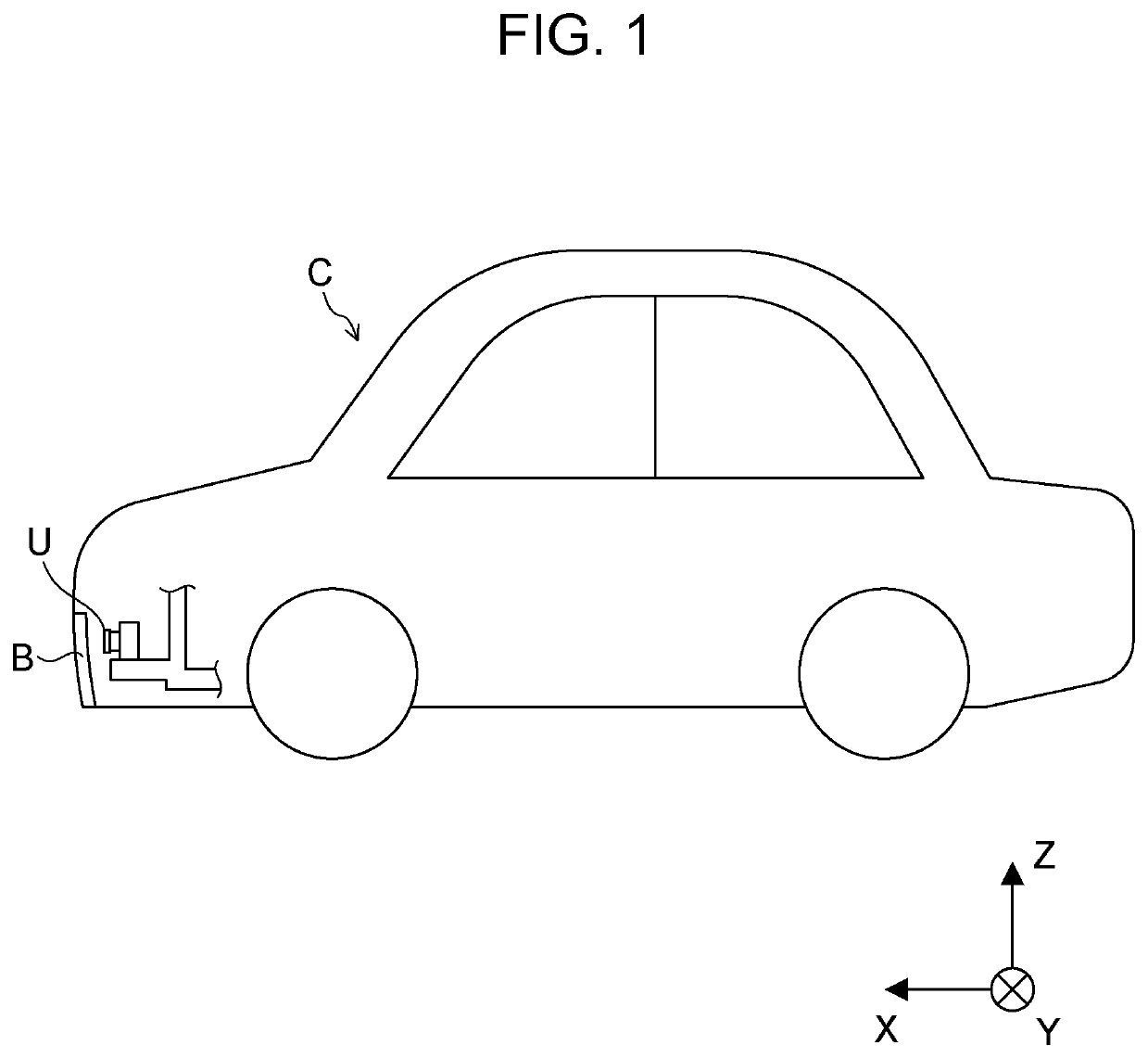
[0023]FIG. 1 is a diagram illustrating an example in which a radar device U according to this embodiment is disposed in a vehicle.
[0024]For example, the radar device U according to this embodiment is disposed in a cover member B (here, a bumper member B) of a vehicle C and performs transmission and reception of electromagnetic waves through the cover member B.
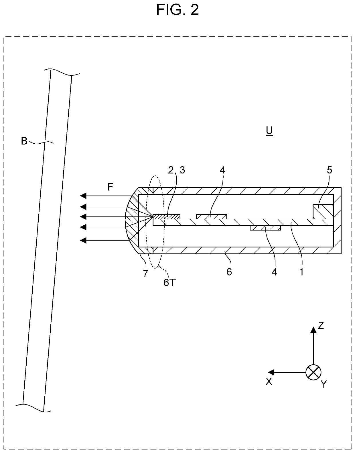
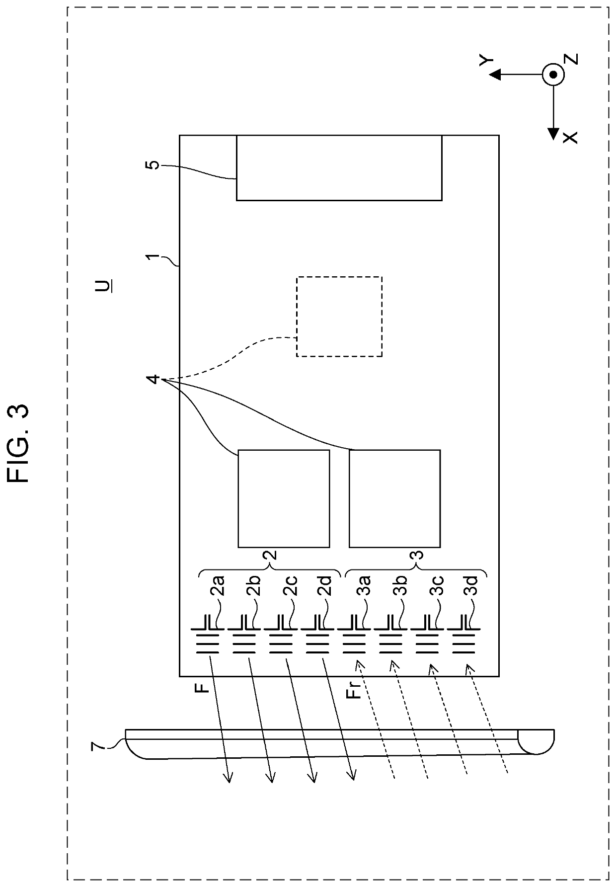
[0025]FIG. 2 is a side sectional view illustrating an example of a configuration of the radar device U according to this embodiment. FIG. 3 is a view of the radar device U according to this embodiment seen from above.
[0026]Solid arrows F in FIGS. 2 and 3 represent the electromagnetic waves transmitted by a transmitting antenna. Dotted line arrows Fr represent the re...
second embodiment
[0062]FIG. 5 is a side sectional view illustrating an example of a configuration of a radar device U according to a second embodiment.
[0063]The radar device U according to this embodiment is different from the radar device U according to the first embodiment in that the radar device U according to this embodiment has a bracket 8 for fixing the housing 6 and the like to the cover member B. Descriptions of configurations common to the first embodiment are omitted (the same applies hereinafter for other embodiments).
[0064]The bracket 8 holds the housing 6 with respect to the cover member B and defines the direction in which the radar device U transmits and receives the electromagnetic waves.
[0065]The bracket 8 has, for example, a storage part 8a that stores the radar device U and fixing parts 8b that are fixed to the cover member B.
[0066]For example, the storage part 8a is in a cylindrical shape that allows the housing 6 to be inserted therein from the front surface (i.e., surface on w...
third embodiment
[0071]FIG. 6 is a side sectional view illustrating an example of a configuration of a radar device U according to a third embodiment.
[0072]The radar device U according to this embodiment is different from the radar device U according to the first embodiment in that the housing 6 has connection units 6a that are thermally bonded to the circuit board 1 or circuit parts mounted on the circuit board 1.
[0073]FIG. 6 illustrates a state where the connection units 6a thermally bond the walls of the housing 6 and the signal processing ICs 4. Arrows T in FIG. 6 represent heat flows from the circuit board 1.
[0074]In this embodiment, material of the housing 6 is a metal member with high heat dissipation characteristics, for example. The connection units 6a thermally bond the walls of the housing 6 and the circuit board 1 or the circuit parts (in this case, signal processing ICs 4) mounted on the circuit board 1.
[0075]The configuration of the connection units 6a is not limited; for example, the ...
PUM
 Abstract
Description
Claims
Application Information
 - R&D
- Intellectual Property
- Life Sciences
- Materials
- Tech Scout
- Unparalleled Data Quality
- Higher Quality Content
- 60% Fewer Hallucinations
Browse by: Latest US Patents, China's latest patents, Technical Efficacy Thesaurus, Application Domain, Technology Topic, Popular Technical Reports.
© 2025 PatSnap. All rights reserved.Legal|Privacy policy|Modern Slavery Act Transparency Statement|Sitemap|About US| Contact US: help@patsnap.com


