
Electric power storage system

a technology of electric power storage and electric power, which is applied in the direction of battery/fuel cell control arrangement, secondary cell servicing/maintenance, instruments, etc., can solve the problems of affecting the accuracy of voltage diagnosis, unable to supply electric power from the electric power storage device to the electrical load (a drive unit) of the vehicle, etc., to achieve high charging efficiency, increase the charging efficiency of the electric power storage device, and reduce the amount of electric power storag

Active Publication Date: 2021-04-13
TOYOTA JIDOSHA KK
View PDF39 Cites 5 Cited by
  • Summary
  • Abstract
  • Description
  • Claims
  • Application Information

AI Technical Summary

Benefits of technology

This approach improves the accuracy of voltage diagnosis, prevents charging of abnormal batteries, and enhances charging efficiency by optimizing the connection state of battery packs during charging, reducing current flow and heat generation.

Problems solved by technology

However, when the voltage range is set as the wide range, accuracy of the voltage diagnosis is possibly degraded.
When the main relay is in the opened state, the electric power cannot be supplied from the electric power storage device to the electrical load (a drive unit) of the vehicle.

Method used


Image

  • Electric power storage system
  • Electric power storage system
  • Electric power storage system

Examples


first modified example

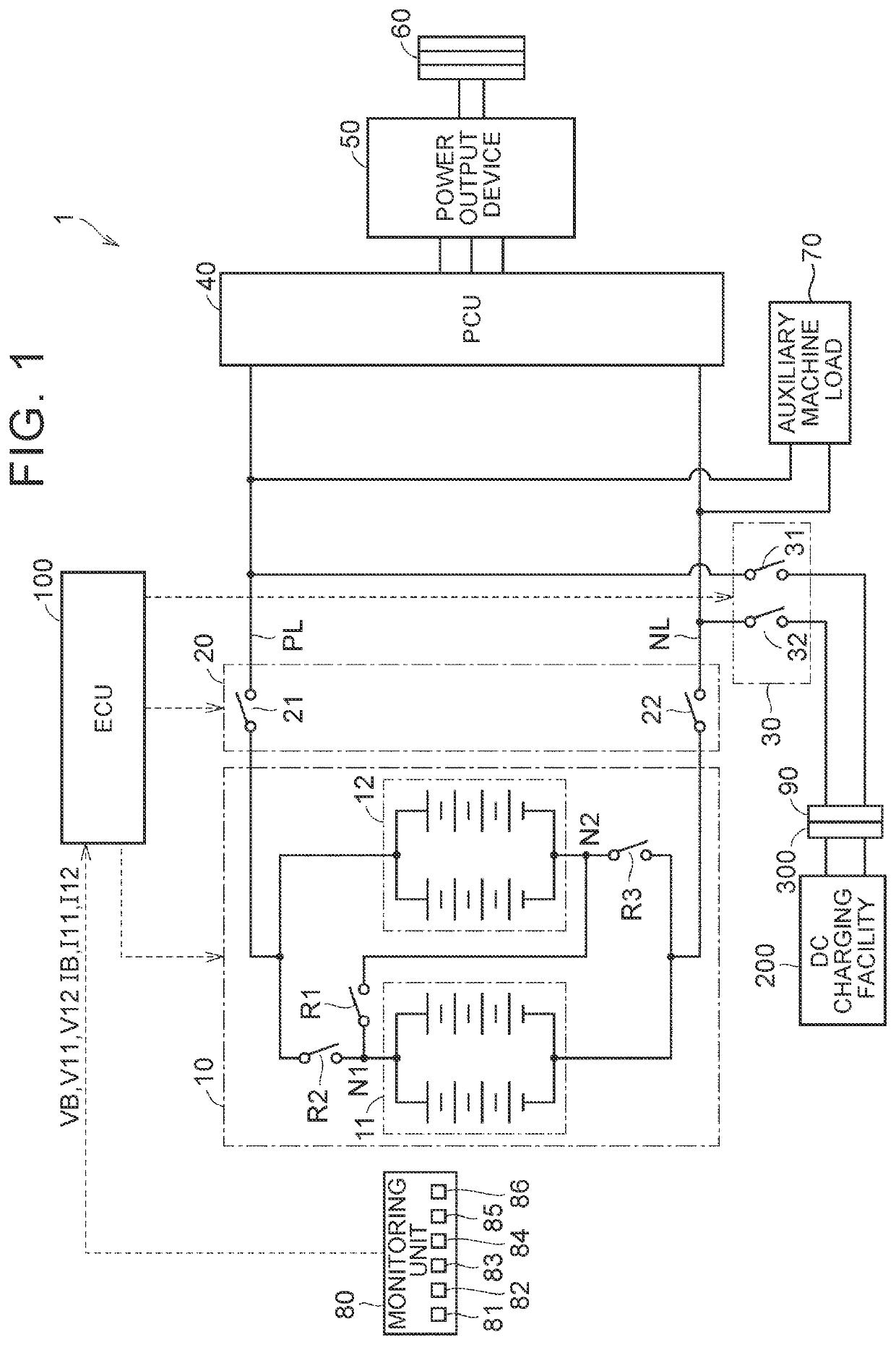
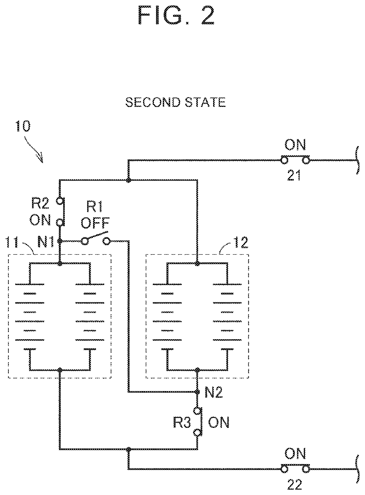
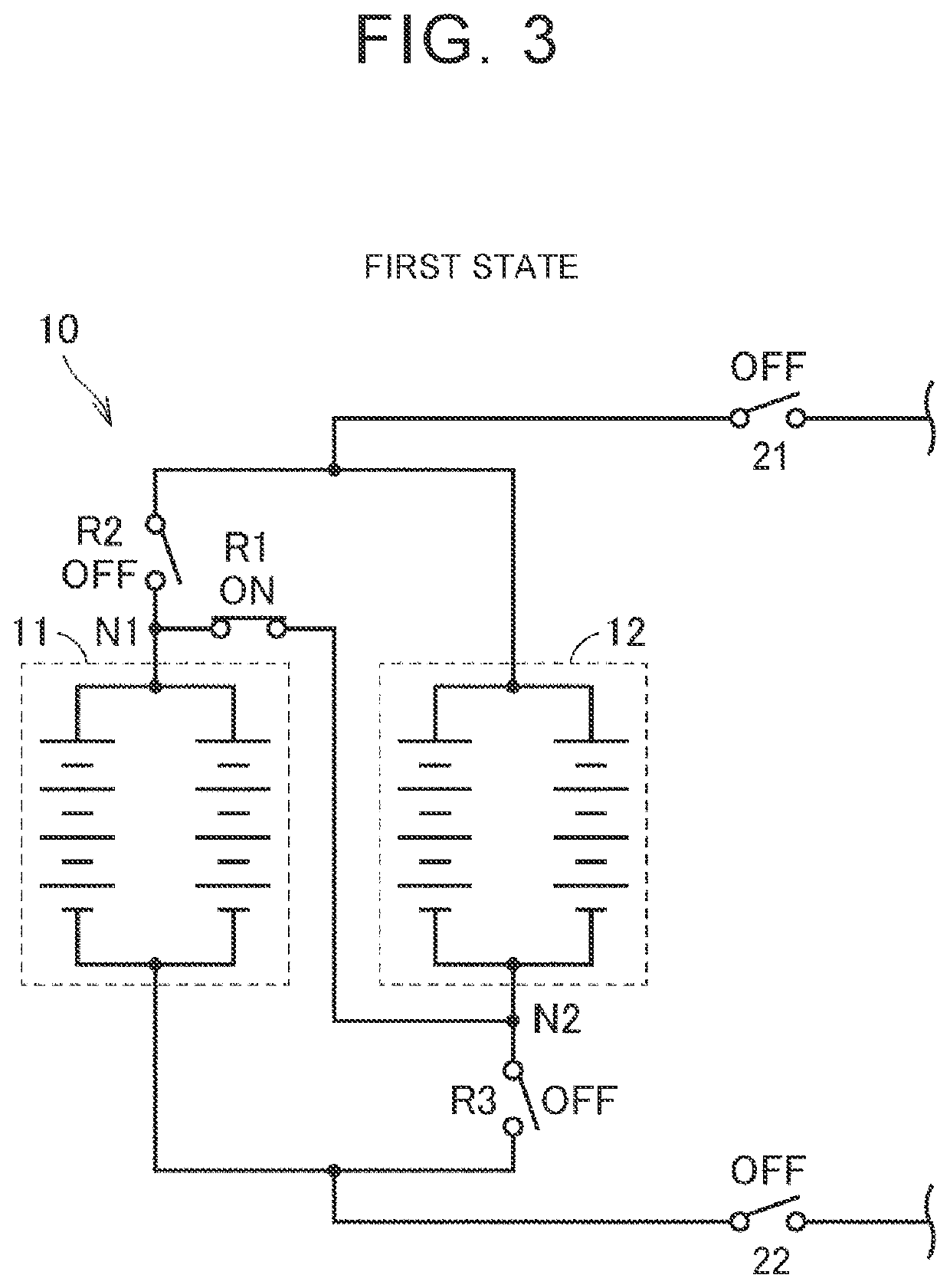
[0100]In the above embodiment, an electric power storage amount such as the SOC of each of the battery packs 11, 12 before the initiation of charging is not considered, and the states of the switching relays R1, R2, R3 at the initiation of charging are determined on the basis of a relationship with the maximum charging voltage of the DC charging facility 200 (more specifically, S235 to S245 in FIG. 8). However, the states of the switching relays R1, R2, R3 may be determined in consideration of the electric power storage amount such as the SOC of each of the battery packs 11, 12. In this way, as will be described below, the vehicle 1 can be charged at the high charging efficiency.

[0101]FIG. 9 includes graphs indicative of a relationship between the SOC of each of the battery packs and an allowable charging current. In FIG. 9, a horizontal, axis of art upper graph represents the SOC of the battery packs, and a vertical axis represents the allowable charging current.

[0102]The graph in ...

second modified example

[0119]In the embodiment and First Modified Example, the description has been made on the example in which the plug-in operation is performed in the READY-OFF state. That is, the description has been made on the example in which the vehicle 1 is switched from the READY-OFF state to the external charging state by the plug-in operation. However, in the electrically-driven vehicle, the plug-in operation may be performed in the READY-ON state of the vehicle 1. That is, the vehicle 1 may be switched front the READY-ON state to the external charging state by the plug-in operation. In Second Modified Example, a description will be made on an example in which the plug-in operation is performed in the READY-ON state.

[0120]FIG. 11 is a timing chart that shows the change in the voltage V13 between the terminals of the electric power storage device 10. In FIG. 11, a horizontal axis represents the time, and a vertical axis represents the voltage. The “second state” indicated in the vertical axis ...


PUM

PropertyMeasurementUnit
voltageaaaaaaaaaa
voltageaaaaaaaaaa
charging electric poweraaaaaaaaaa

Abstract

The electric power storage device of an electric power storage system includes plural electric power storage bodies and a switching relay. The switching relay is capable of being switched between a first state where the plural electric power storage bodies are connected in series, and a second state where the plural electric power storage bodies are connected in parallel. The switching relay allows each of the plural electric power storage bodies to be electrically disconnected from the rest of the electric power storage bodies. The control unit controls the switching relay into the all-off state where the plural electric power storage bodies are electrically disconnected from each other, when the main relay is in an opened state.

Description

CROSS-REFERENCE TO RELATED APPLICATION[0001]This application claims priority to Japanese Patent Application No. 2018-008334 filed on Jan. 22, 2018, incorporated herein by reference in its entirety.BACKGROUND1. Technical Field[0002]The present disclosure relates to an electric power storage system capable of charging an electric power storage device mounted on a vehicle by using a power supply provided on the outside of the vehicle.2. Description of Related Art[0003]In Japanese Patent Application Publication No. 2013-81316 (JP 2013-81316 A), a vehicle that includes an electric power storage device configured to be charged by receiving electric power supplied from a power supply on the outside of the vehicle has been disclosed. The electric power storage device provided in the vehicle includes: plural battery packs; and a relay capable of being switched to ore of a fa it state where the plural battery packs are connected in series and a second state v the plural battery packs are conn...

Claims


Application Information

Patent Timeline
Patent Type & Authority Patents(United States)
IPC IPC(8): B60L58/19B60L50/15H01M10/44H01M10/48G01R31/382B60K1/04B60W10/26H02J7/00B60L53/20B60L58/15B60L3/00
CPCB60L58/19B60K1/04B60L3/0046B60L50/15B60L53/20B60L58/15B60W10/26G01R31/382H01M10/44H01M10/48H02J7/0024H02J7/0047H02J7/0026B60L58/13Y02T10/70Y02T90/14Y02T10/7072Y02E60/10
Inventor HIROE, YOSHIHIKONIIMI, YOSHITAKA
Owner TOYOTA JIDOSHA KK
Learn More