
Pull or push rod or a locking nut for a molding machine

a molding machine and locking nut technology, applied in the direction of nuts, screws, bolts, etc., can solve the problems of increased danger, related undercuts before or after the groove, etc., and achieve the effect of reducing material expenditure, essentially maintaining strength, and increasing strength

Active Publication Date: 2021-04-13
ENGEL AUSTRIA
View PDF30 Cites 0 Cited by
  • Summary
  • Abstract
  • Description
  • Claims
  • Application Information

AI Technical Summary

Benefits of technology

The solution enhances strength while minimizing material expenditure, allowing for increased clearance between rods and improved structural efficiency under high clamping forces.

Problems solved by technology

Here the grooves in the pull or push rods represent a notch, and thus form a cross-section with the highest load in the groove cross-section, the related undercuts before or after the grooves, however, are also increased sources of danger.

Method used


Image

  • Pull or push rod or a locking nut for a molding machine

Examples


Embodiment Construction

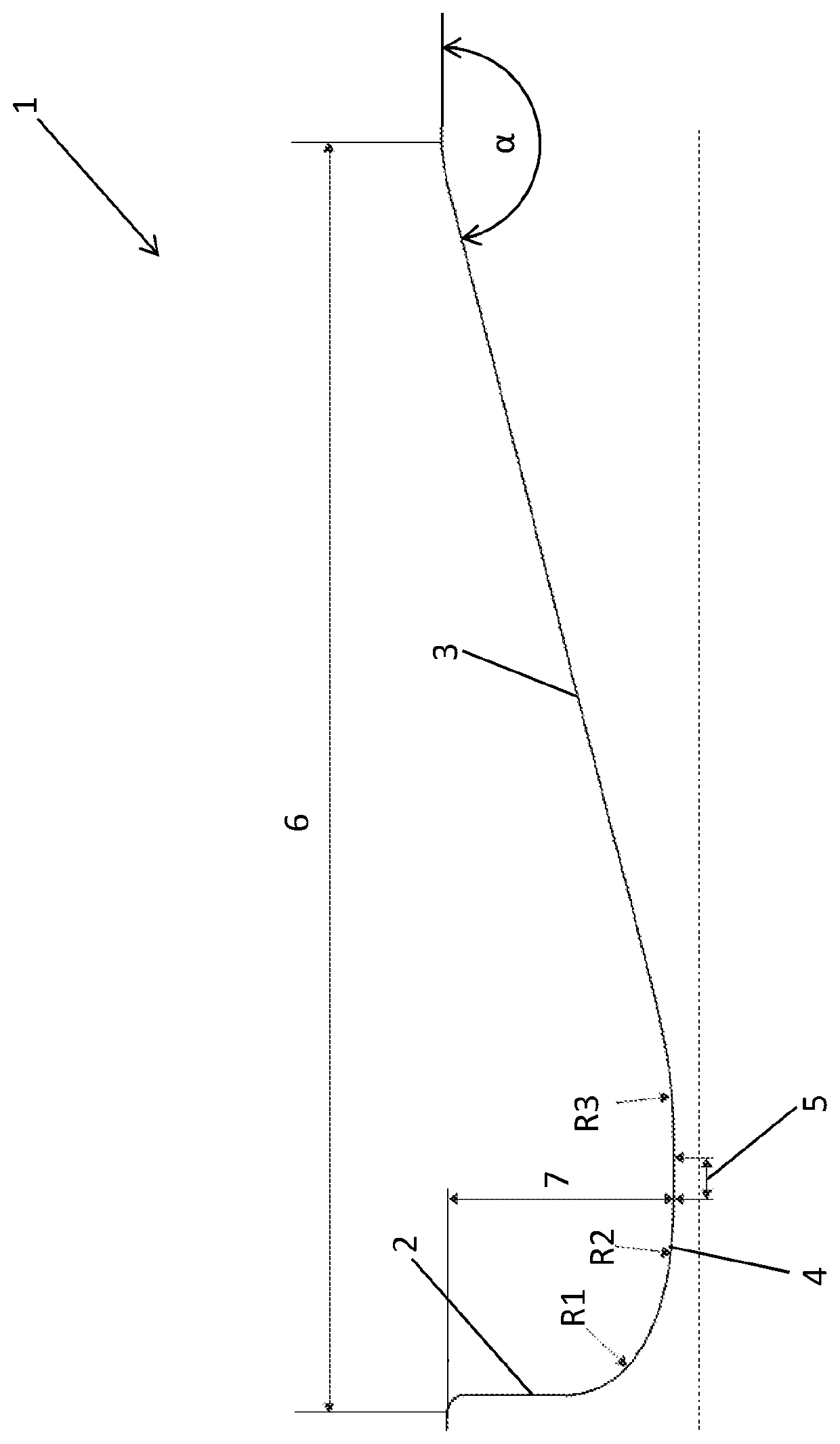
[0041]FIG. 1 shows a partial view of a pull or push rod or locking nut according to the invention with an undercut 1 in cross-section (in undercut cross-section). The undercut 1 is formed by a side wall 2, an undercut base 4, and an undercut ramp 3. Here the side wall 2 transitions tangentially into a first transition curvature (in this embodiment shown as transition radius R1), which in turn transitions tangentially into the curvature of the undercut base 4 (which in this embodiment is designated the radius R2). The undercut base 4 or the radius R2 transitions tangentially into the second transition. This second transition is hereby designed two-part. First, by a straight-lined section 5, which is directly adjacent to the undercut base 4, which in turn transitions tangentially into the transition curvature (shown here as transition radius R3), which connects the straight-lined undercut ramp 3 tangentially. The undercut ramp 3 is inclined at an angle α to the surface of the pull or ...


PUM

PropertyMeasurementUnit
angleaaaaaaaaaa
angleaaaaaaaaaa
angleaaaaaaaaaa

Abstract

A pull or push rod or locking nut for a molding machine has an undercut, and the undercut has an undercut cross-section, a side wall, and an undercut ramp. The side wall transitions via a first transition curvature into an undercut base, and the undercut base transitions via a second transition curvature into the undercut ramp. The undercut base, viewed in the undercut cross-section, is at least partially curved, and the curvature of the undercut base differs from the first transition curvature and / or the second transition curvature.

Description

BACKGROUND OF THE INVENTION[0001]The invention concerns a pull or push rod or a locking nut for a molding machine with at least one groove, a clamping unit of a molding machine or a molding machine with a clamping unit, and a method of producing a pull or push rod or a locking nut for a molding machine.[0002]Molding machines can be understood as injection molding machines, transfer molding machines, presses or the like.[0003]In the following, the prior art is explained using an example of an injection molding machine.[0004]An injection process typically begins with the closing of the clamping unit, and the movable mold mounting plate is brought to the fixed mold mounting plate by a rapid stroke movement. The movable mold mounting plate is then locked with the pressure-exerting piston part of a clamping mechanism, and the clamping mechanism builds up the clamping force required for the injection process.[0005]In the case of an injection molding machine with a tie bar, the clamping me...

Claims


Application Information

Patent Timeline
Patent Type & Authority Patents(United States)
IPC IPC(8): F16B39/30B29C45/67B29C45/66
CPCB29C45/6714B29C45/66B29C45/6728F16B39/30B29C45/68B29C45/26B23P15/00
Inventor SCHOTT, GUENTERSTOEGER, MARKUSCZEPL, RICHARDZEIDLHOFER, HERBERT
Owner ENGEL AUSTRIA
Learn More