Multi-fiber connector visual polarity and continuity tester
a multi-fiber connector and visual polarity and continuity technology, applied in the field of fiber optic cable polarity and continuity testers, can solve the problem that intelligent receivers are much more expensive than passive receivers
- Summary
- Abstract
- Description
- Claims
- Application Information
AI Technical Summary
Benefits of technology
Problems solved by technology
Method used
Image
Examples
Embodiment Construction
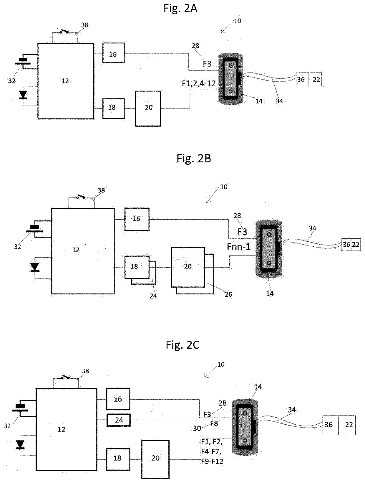
[0020]Referring first to FIG. 2A, a diagram of the test device 10 of the present invention configured for testing the fibers of a twelve fiber cable 34 is provided. Cable 34 houses twelve fibers, each of which terminate at both first connector 14 and second connector 36. Controller 12 is powered by power source 32, which is preferably a battery, such as an AA-sized or rechargeable battery, but may be any power source commonly used in the art. Controller 12 has power switch 38. First light source 16 sends a first light pattern into a single fiber 28 at position 3 (“F3”) at first connector 14. Second light source 18 is split by optical splitter 20 so that the second light pattern of second light source 18 is sent through every other fiber in cable 34 (“F1, 2, 4-12”). Optical splitter 20 is preferably a standard 1×N splitter, but may be any optical splitter commonly used in the art. The “N” in a 1×N splitter is the maximum number of portions into which that splitter may split the light...
PUM
 Abstract
Description
Claims
Application Information
 - R&D
- Intellectual Property
- Life Sciences
- Materials
- Tech Scout
- Unparalleled Data Quality
- Higher Quality Content
- 60% Fewer Hallucinations
Browse by: Latest US Patents, China's latest patents, Technical Efficacy Thesaurus, Application Domain, Technology Topic, Popular Technical Reports.
© 2025 PatSnap. All rights reserved.Legal|Privacy policy|Modern Slavery Act Transparency Statement|Sitemap|About US| Contact US: help@patsnap.com


