Smart and robust wall socket with integrated universal serial bus (USB)

a wall socket and serial bus technology, applied in the direction of coupling device connection, power network operation system integration, printed circuit aspects, etc., can solve the problem that the ability typically requires corresponding circuit complexity, and achieve the effect of reducing resistan

Active Publication Date: 2021-03-23
COMPUTIME LTD
View PDF18 Cites 0 Cited by
  • Summary
  • Abstract
  • Description
  • Claims
  • Application Information

AI Technical Summary

Problems solved by technology

However, these capabilities typically require corresponding circuit complexity while supplying substantial electrical power under high and varying current loads to the attached appliance.

Method used


Image

  • Smart and robust wall socket with integrated universal serial bus (USB)
  • Smart and robust wall socket with integrated universal serial bus (USB)
  • Smart and robust wall socket with integrated universal serial bus (USB)

Examples


first embodiment

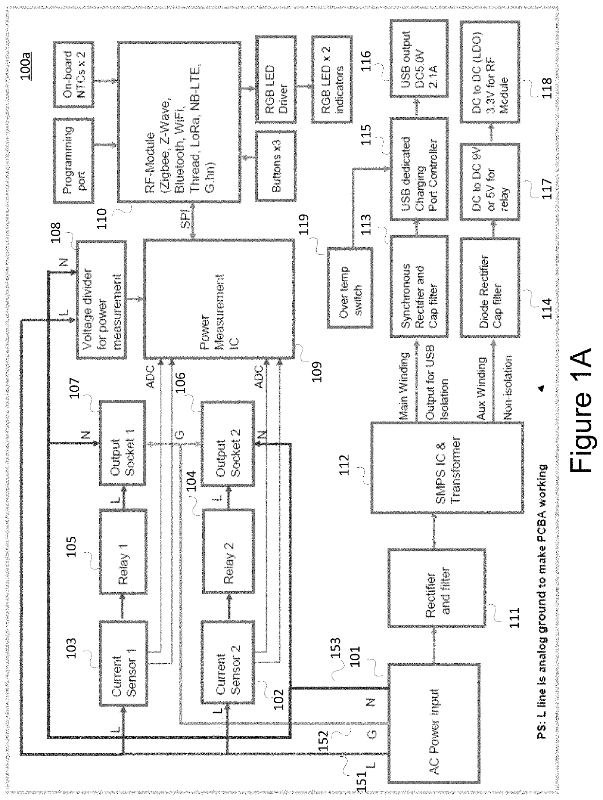
[0052]With a first embodiment, a smart socket structure comprises a relay, a power measurement IC, a current sensor, an RF module, an AC / DC converter, a microcontroller unit (MCU), at least one socket, a grounding metal bracket, and a plastic housing.

second embodiment

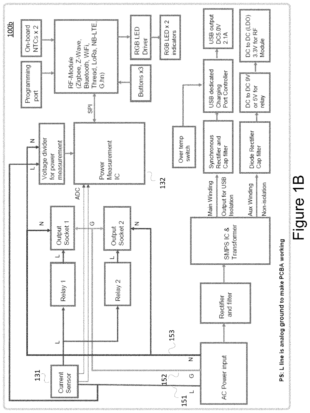
[0053]With a second embodiment, a smart socket comprises two sockets with two integrated USB outlets.

third embodiment

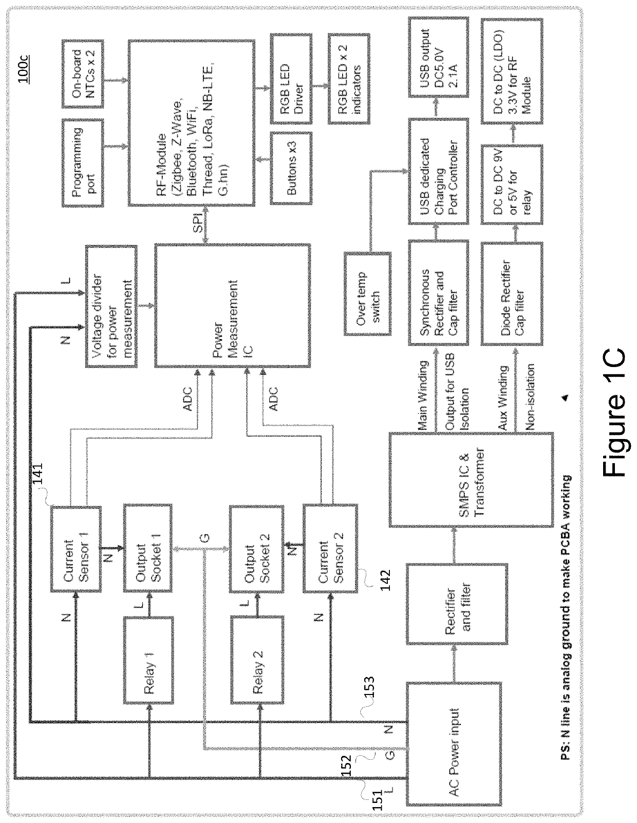
[0054]With a third embodiment, a smart socket comprises two smart sockets, where each socket has its own current sensor for energy measurement and reporting with both current sensors and relays on a Live (L) lines\ as shown in FIG. 1A.


PUM


Abstract

A smart electrical plug supports one or more electrical outlets and one or more universal serial bus (USB) outlets for charging electrical devices. Electrical power consumed through the one or more electrical outlets may be measured individually or in combination and reported via a wireless communication channel. The smart electrical plug may be implemented by a plurality of printed circuit board assemblies and distributed within a housing to reduce the effects of heat dissipation. The smart electrical plug may further reduce heat dissipation by utilizing one or more electrical circuit approaches.

Description

[0001]This patent application claims priority to U.S. provisional patent application Ser. No. 62 / 551,334 entitled “Smart and Robust Wall Socket with Integrated Universal Serial Bus (USB)” filed on Aug. 29, 2017, which is hereby incorporated by reference in its entirety.TECHNICAL FIELD[0002]Aspects of the disclosure relate to a smart electrical plug that provides electrical power to an attached electrical device such as an appliance.BACKGROUND OF THE INVENTION[0003]A smart plug is typically a device that plugs right into an ordinary outlet and has its own outlet. An appliance may be plugged into the smart plug's outlet to obtain enhancements with respect to the ordinary electrical outlet. For example, a stuart plug may, via an app, enable a user to actively control it, automate it according to a time schedule, or trigger it from another electronic system.[0004]Smart plugs may be a versatile building block of the smart home, with numerous uses for security, convenience, and energy sav...

Claims


Application Information

Patent Timeline
Patent Type & Authority Patents(United States)
IPC IPC(8): H01R13/66H01R13/713H01R25/00H05K1/14H02J3/14H05K5/00G01R19/25H01R27/02H02J7/00
CPCH01R13/6675H01R13/6683H01R13/6691H01R13/713H01R25/006H02J3/14H05K1/14G01R19/2513H01R13/7137H01R27/02H02J7/00H02J2310/14H05K5/0026H05K2201/1003H05K2201/10053H05K2201/10151H05K2201/10189H05K2201/10325H01R13/665H01R31/065Y04S20/222Y04S20/242Y02B70/30Y02B70/3225
Inventor YILMAZ, HAMZACHOI, HUNG BUNHO, MICHAELXU, JERRYZHOU, FPTAO, TOMCHEN, ZHLIU, KEVIN
Owner COMPUTIME LTD
Why Eureka
Try Eureka