Magnetic microfluidic concentrator, intelligent magnetic microfluidic concentrator, and complete set of beneficiation equipment using the same

a technology of magnetic microfluidic concentrator and magnetic microfluidic concentrator, which is applied in the field of magnetic separation, can solve the problems of iron ore market downturn, production cost, and iron concentrate powder production cost that can only be reduced by upgrading the beneficiation process, and achieves improved grade, improved separation efficiency and precision.

Active Publication Date: 2021-03-16
LONGI MAGNET CO LTD
View PDF7 Cites 0 Cited by
  • Summary
  • Abstract
  • Description
  • Claims
  • Application Information

AI Technical Summary

Benefits of technology

[0007]In order to solve the above problems, the inventors have proposed, after repeated designs and researches, a magnetic microfluidic concentrator, an intelligent magnetic microfluidic concentrator, and a complete set of beneficiation equipment, which are used in a beneficiation plant for sorting magnetic ores, and have the advantages of high extent of grade upgrading, high recovery rate, large processing capacity, low water consumption, high automation, etc.
[0019]The magnetic microfluidic concentrator, the intelligent magnetic microfluidic concentrator, and the complete set of beneficiation equipment using the same disclosed in the present disclosure have the advantages of solving the disadvantage that the traditional magnetic gravity separation equipment such as a magnetic separation column, an elutriation machine or the like, although having the considerable grade improving capability, but cannot control entrainment of impurities well and consumes a large amount of water during the sorting process. Accurate sorting is achieved in the present disclosure by precisely controlling the magnetic field and water flow. Magnetic particles and impurities can be separated more effectively and precisely, resulting in ore concentrates with higher grade and higher recovery rate. Moreover, the present disclosure is highly automated and consumes a small amount of water, and can reduce more beneficiation cost for the beneficiation plant. Further, the present disclosure has a simple structure and reasonable design, fills a vacancy for such magnetic gravity separation equipment, and is worthy of wide popularization and application.

Problems solved by technology

With the trend that the iron ore market is downturn in recent years or in long term and the oversupply of iron ore, improving a beneficiation process and reducing the production cost of iron concentrate powder have become urgent problems to be solved for all major beneficiation plants.
Since the mines in China are generally poor mines and there are very few rich mines in China, it is almost impossible for most beneficiation plants in China to exploit high-grade raw ores, thus the production cost of iron concentrate powder can only be reduced by upgrading the beneficiation process.
Although traditional magnetic gravity separation equipment such as a magnetic separation column, an elutriation machine or the like has the considerable grade upgrading capability, the problems of entrainment of impurities and water consumption still cannot be controlled well during the sorting process.
Eventually, a large amount of ores are lost in tailings when the grade of ore is increased, so that many high-grade magnetic particles are also introduced into the tailings.
Moreover, because the sorting process is crude and not precise enough, it leads to large water consumption.
Furthermore, such equipment has a low level of automation and needs to be maintained and adjusted by a large amount of manpower, and the disadvantages such as high loss in tailings, low recovery rate, large water consumption, and large amount of required manpower all increase the production cost of iron concentrate powder.

Method used


Image

  • Magnetic microfluidic concentrator, intelligent magnetic microfluidic concentrator, and complete set of beneficiation equipment using the same
  • Magnetic microfluidic concentrator, intelligent magnetic microfluidic concentrator, and complete set of beneficiation equipment using the same
  • Magnetic microfluidic concentrator, intelligent magnetic microfluidic concentrator, and complete set of beneficiation equipment using the same

Examples


Embodiment Construction

[0023]The technical solutions of embodiments of the present disclosure will be described below clearly and completely with reference to the drawings of the embodiments of the present disclosure. It is apparent that the embodiments described are some, but not all of the embodiments of the present disclosure. All the other embodiments obtained by those of ordinary skill in the art in light of the embodiments of the present disclosure without inventive efforts should fall within the scope of the present disclosure as claimed. In addition, the scope of protection of the present disclosure should not be limited only to the specific structures or components or specific parameters described below.

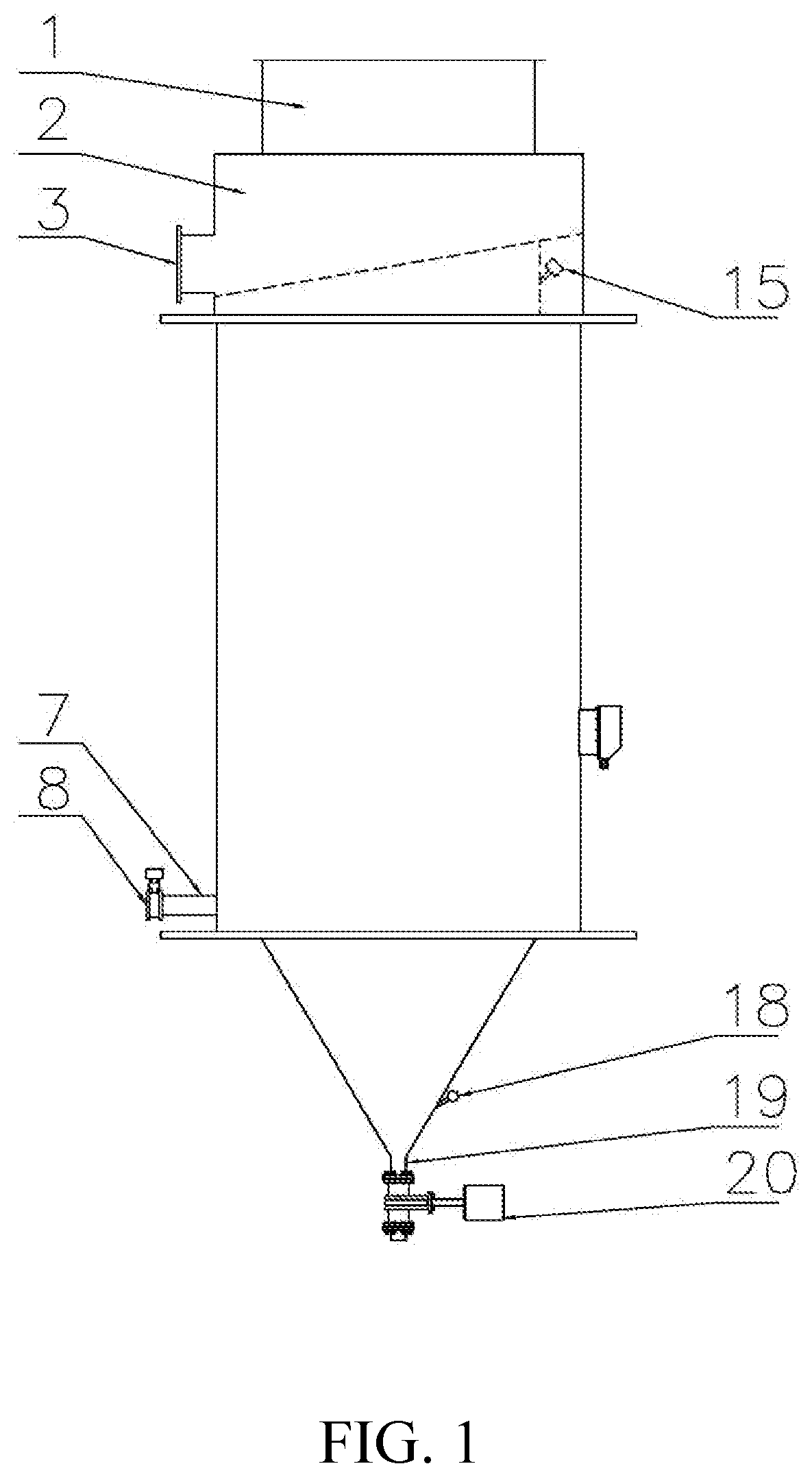
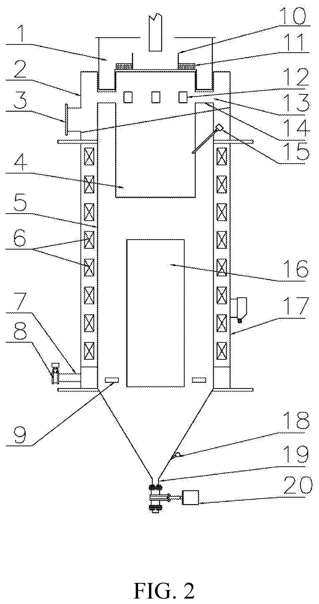
[0024]The present disclosure discloses an intelligent magnetic microfluidic concentrator, which mainly has a sorting system consisting of an ore feeding chute 1, an overflow chute 2, an overflow tank 4, a sorting tank 5 and a magnetic system 6; and has an equipment control system, wherein an ore c...


PUM

PropertyMeasurementUnit
distanceaaaaaaaaaa
shapeaaaaaaaaaa
sizeaaaaaaaaaa

Abstract

An intelligent magnetic microfluidic concentrator employs a technique of feeding ores circumferentially and allowing tailings to overflow centrally upward. The intelligent magnetic microfluidic concentrator comprises a sorting system consisting of an ore feeding chute, an overflow chute, an overflow tank, a sorting tank, and a magnetic system, the overflow tank is disposed at an upper portion of the sorting tank, the ore feeding chute is disposed at the top of the overflow tank, the ore feeding chute feeds an ore slurry to the upper portion of the sorting tank circumferentially along an inner wall of the sorting tank, and the tailings overflow out upward from the overflow tank disposed centrally and located at the upper half portion of the sorting tank. A magnetic microfluidic concentrator and a complete set of beneficiation equipment are also provided.

Description

[0001]This application claims priority to Chinese Patent Application No. 201711067728.6, filed with the Chinese Patent Office on Nov. 3, 2017, entitled “Magnetic Microfluidic Concentrator and Complete Set of Beneficiation Equipment Using the Same”, which is incorporated herein by reference in its entirety.TECHNICAL FIELD[0002]The present disclosure pertains to the technical field of magnetic separation, and in particular relates to a magnetic microfluidic concentrator, an intelligent magnetic microfluidic concentrator, and a complete set of beneficiation equipment using the same, belonging to novel intelligent electromagnetic separation equipment.BACKGROUND ART[0003]With the trend that the iron ore market is downturn in recent years or in long term and the oversupply of iron ore, improving a beneficiation process and reducing the production cost of iron concentrate powder have become urgent problems to be solved for all major beneficiation plants.[0004]The reduction of the productio...

Claims


Application Information

Patent Timeline
Patent Type & Authority Patents(United States)
IPC IPC(8): B03C1/28B03C1/30B03D1/001B01D21/00
CPCB03C1/286B03C1/30B03D1/001B01D21/0009B03C1/284B03C1/288B03C1/02B01D21/2416B01D21/2433B01D21/302B01D2221/04B03C1/32B03C2201/18B03D1/028B03D1/1456B03D1/1462B03D2203/02C22B7/04
Inventor ZHANG, CHENGCHENLI, HENGSHENGZHENG, DELIANGWANG, CHAOSUN, SHIXINZHU, DONGFANG
Owner LONGI MAGNET CO LTD
Why Eureka
Try Eureka