
Systems and methods for parallel channel microfluidic separation

a microfluidic separation and parallel channel technology, applied in sedimentation separation, other medical devices, separation processes, etc., can solve the problems of blood cell damage, device failure to deliver continuous flow cleansing devices, and blood cell damage, so as to increase the access to life-saving therapy and reduce costs

Active Publication Date: 2021-03-16
CHARLES STARK DRAPER LABORATORY
View PDF28 Cites 1 Cited by
  • Summary
  • Abstract
  • Description
  • Claims
  • Application Information

AI Technical Summary

Benefits of technology

The present solution is a method to purify lymphocytes, including T-cells, from patient blood samples using an acoustic device. This method can reduce costs and increase access to life-saving therapy. It can separate lymphocytes at high rates using a polystyrene acoustophoretic device that can accept standard leukapheresis product with only 1:1 dilution and is tunable. The system can recover about 72% of lymphocytes with 90.4% purity in a high-recovery mode and about 43% of lymphocytes with a 96.8% purity in a high-purity mode. The performance of this device exceeds that achieved by existing centrifugal methods. Additionally, the solution can achieve a high efficiency of about 80% to about 90% red blood cell (RBC) separation at rates between about 0.5 and about 2 mL / min.

Problems solved by technology

The concept of blood cleansing and separation has been tried previously but remains laborious.
These devices have failed to deliver continuous flow cleansing devices.
In addition to often discarding large portions of the blood, current cleansing devices may rely on: diluents, sheath flow, controlled solution conductivity, costly microfabricated on-chip materials, and toxic additives.
The current isolation practice can involve laborious centrifugal separation under highly controlled conditions, which can damage the blood cells.

Method used


Image

  • Systems and methods for parallel channel microfluidic separation
  • Systems and methods for parallel channel microfluidic separation
  • Systems and methods for parallel channel microfluidic separation

Examples


Embodiment Construction

"d_n">[0032]The various concepts introduced above and discussed in greater detail below may be implemented in any of numerous ways, as the described concepts are not limited to any particular manner of implementation. Examples of specific implementations and applications are provided primarily for illustrative purposes.

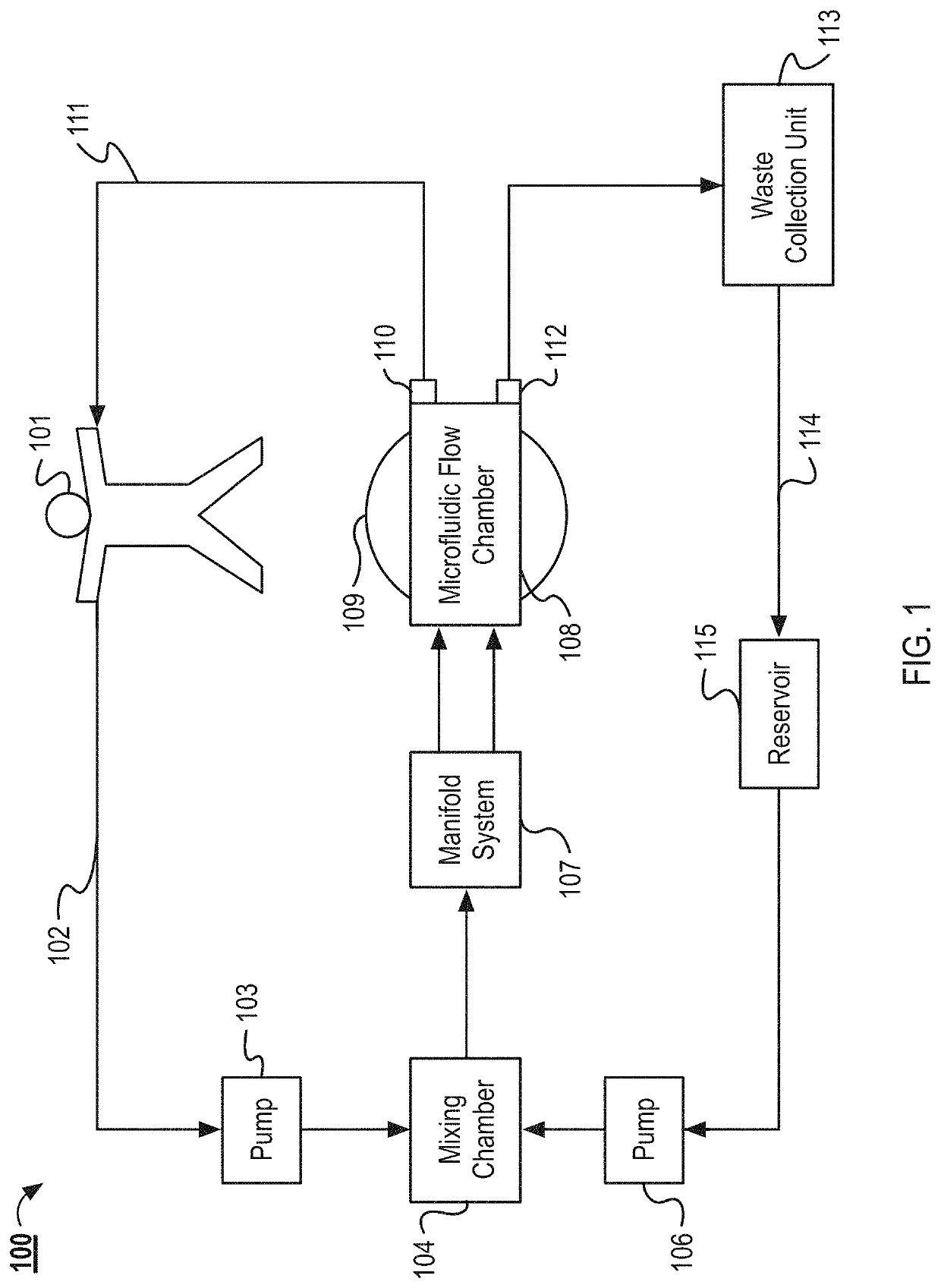
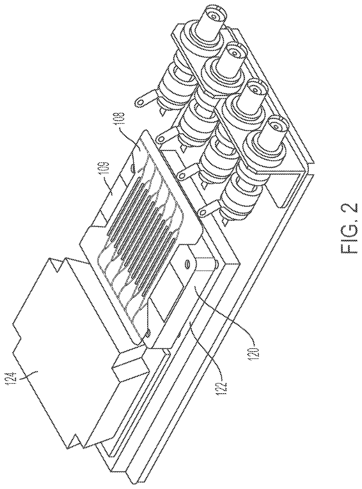
[0033]FIG. 1 illustrates an example system 100 for separating the contents of a fluid. In the system 100, blood (or another fluid to be processed) is removed from a patient 101 via an intravenous line 102. The blood is then pumped to a mixing chamber 104 by a pump 103. In the mixing chamber 104, capture particles are mixed with the blood. The components of the capture particles are stored in a reservoir 115. From the reservoir 115, the capture particles are pumped by a pump 106 into the mixing chamber. From the mixing chamber 104, the blood and capture particles enter a manifold system 107. The manifold system 107 distributes the blood and capture particles to a plura...


PUM

PropertyMeasurementUnit
angleaaaaaaaaaa
thicknessaaaaaaaaaa
thicknessaaaaaaaaaa

Abstract

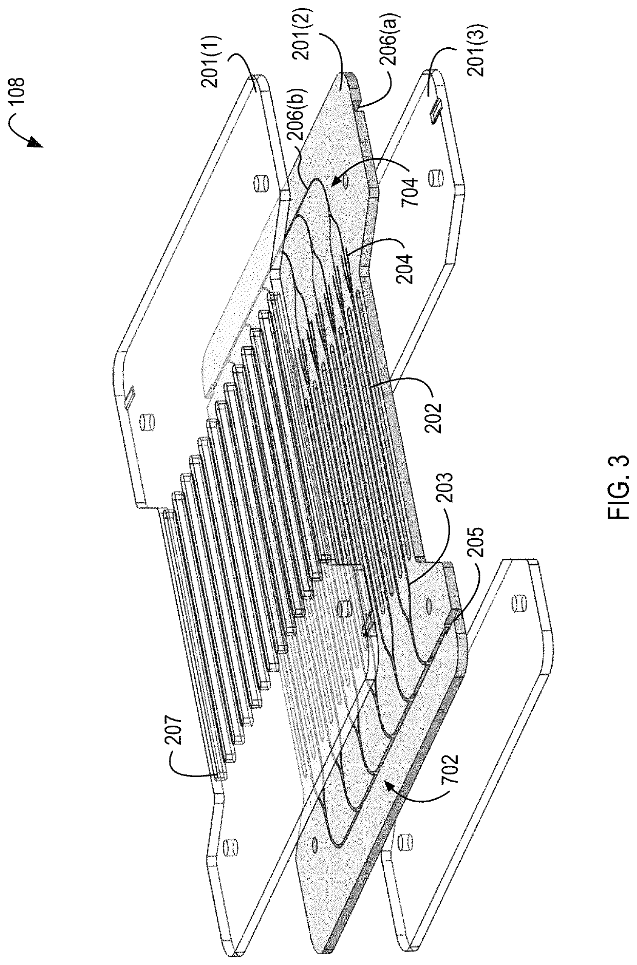
The present disclosure describes a system and method for microfluidic separation. More particularly, the disclosure describes a system and method for the purification of a fluid by the removal of undesired particles. The device includes microfluidic separation channels that include multiple outlets. The device also includes isolation slots positioned between each of the microfluidic separation channels. The device's base includes multiple acoustic transducers which in some implementations are configured to protrude into the isolation slots. The acoustic transducers are configured to generate aggregation axes within the separation channels, which are used to separate out undesired particles.

Description

CROSS-REFERENCE TO RELATED APPLICATIONS[0001]The present application claims the benefit of priority under 35 U.S.C. § 120 as a continuation-in-part of U.S. patent application Ser. No. 14 / 815,501 filed Jul. 31, 2015, which claims the benefit of priority to U.S. Provisional Patent Application No. 62 / 031,662 filed on Jul. 31, 2014. This application also claims the benefit of priority to U.S. Provisional Patent Application No. 62 / 489,560, filed Apr. 25, 2017. Each of the foregoing applications are herein incorporated by reference in their entirety.BACKGROUND[0002]The concept of blood cleansing and separation has been tried previously but remains laborious. Previous blood cleansing concepts have included laboratory scale methods of centrifugation, capillary electrophoresis, liquid chromatography, field flow fractionation, and liquid-liquid extraction. These devices have failed to deliver continuous flow cleansing devices. In addition to often discarding large portions of the blood, curre...

Claims


Application Information

Patent Timeline
Patent Type & Authority Patents(United States)
IPC IPC(8): A61M1/36B01D21/28
CPCA61M1/3678A61M1/365A61M2205/3673B01D21/283A61M1/362A61M1/3623
Inventor FIERING, JASON OLIVERSUN, HOI-CHEONG STEVE
Owner CHARLES STARK DRAPER LABORATORY
Learn More