Eureka AIR delivers breakthrough ideas for toughest innovation challenges, trusted by R&D personnel around the world.

Separator for battery, laminated separator, lithium ion secondary battery, and battery pack

a lithium ion secondary battery and separator technology, applied in the manufacture of final products, cell components, cell component details, etc., can solve the problems of increasing the risk of micro-short circuiting, and achieve the effect of superior input and output characteristics and safety

Active Publication Date: 2021-03-09
TOYOTA JIDOSHA KK
View PDF34 Cites 0 Cited by
  • Summary
  • Abstract
  • Description
  • Claims
  • Application Information

AI Technical Summary

Benefits of technology

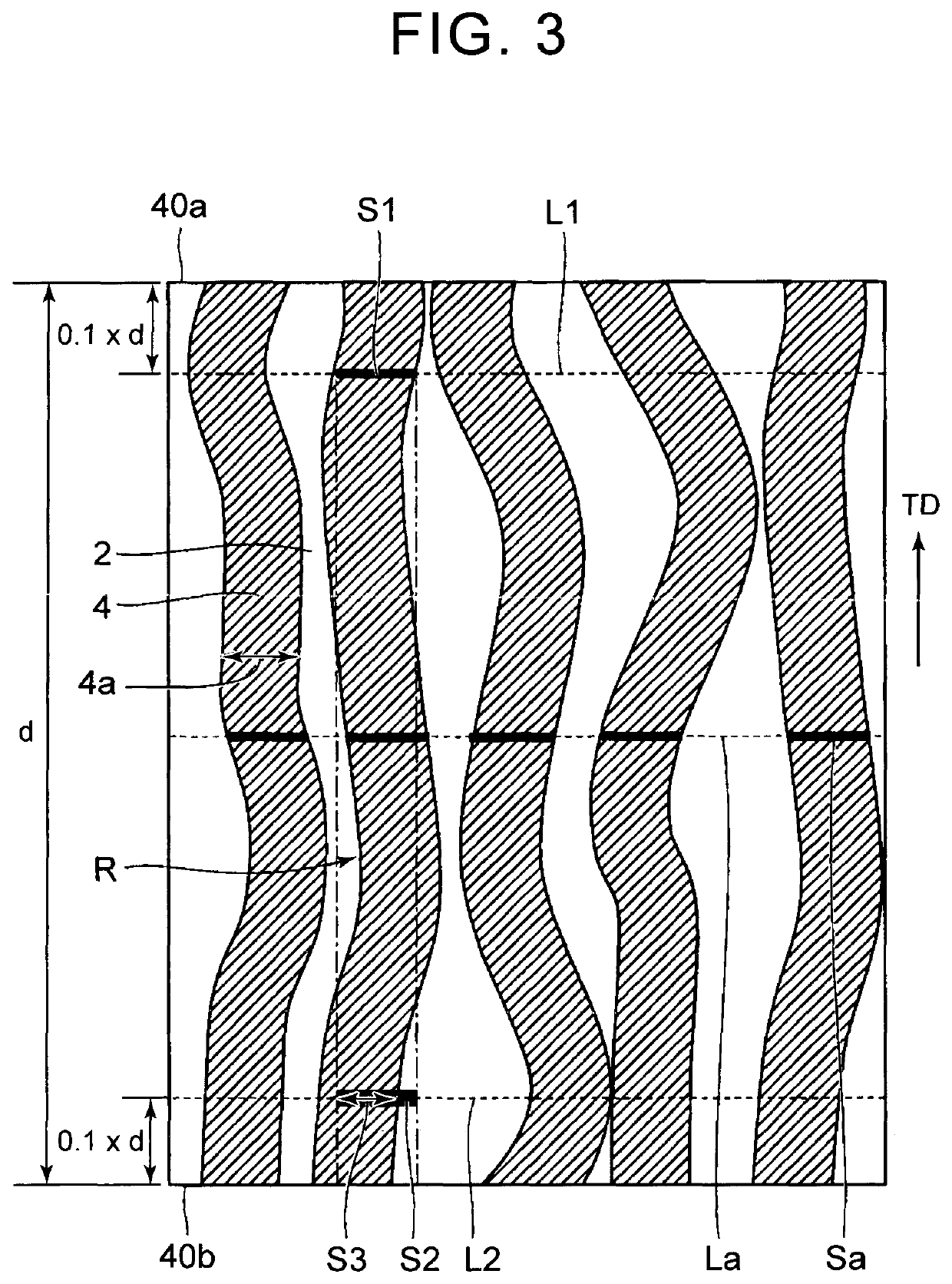
[0011]In a separator for a battery (hereinafter, also referred to simply as “separator”) of the related art, a configuration in which a pore path is linear is avoided. When a separator in which a pore path is linear collapses, the risk of micro-short-circuiting increases. However, in the above-described configuration, the pore path is intentionally made to be linear. That is, referring to FIG. 3, in the above-described separator for a battery, each of resin fibers 4 on a cross-section in a thickness direction TD intersects with a first reference line LI to form a first line segment S1 and also intersects with a second line segment S2 in which a band-shaped region R extending from the first line segment S1 in the thickness direction intersects with a second reference line L2. At this time, a third line segment S3 in which each of the resin fibers 4 intersects with the second line segment S2 accounts for 80% or higher of the second line segment S2.
[0026]According to the embodiments of the invention, it is possible to provide a separator for a battery having superior input and output characteristics and safety; and a laminated separator, a lithium ion secondary battery, and a battery pack in which the separator is used.

Problems solved by technology

When a separator in which a pore path is linear collapses, the risk of micro-short-circuiting increases.

Method used


Image

  • Separator for battery, laminated separator, lithium ion secondary battery, and battery pack
  • Separator for battery, laminated separator, lithium ion secondary battery, and battery pack
  • Separator for battery, laminated separator, lithium ion secondary battery, and battery pack

Examples


first embodiment

ttery

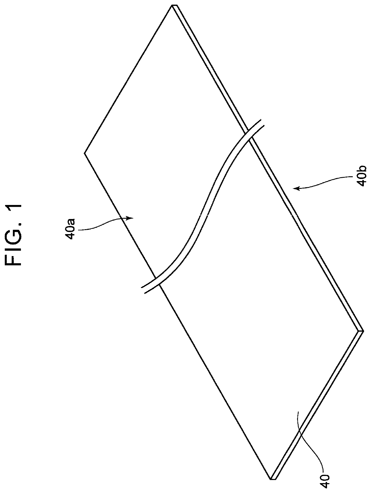
[0045]A first embodiment relates to a separator for a battery. FIG. 1 is a schematic diagram showing a configuration of a separator 40 for a battery. Referring to FIG. 1, the separator 40 for a battery is typically an elongated belt-shaped sheet member and includes a first main surface 40a and a second main surface 40b that is a back surface of the separator.

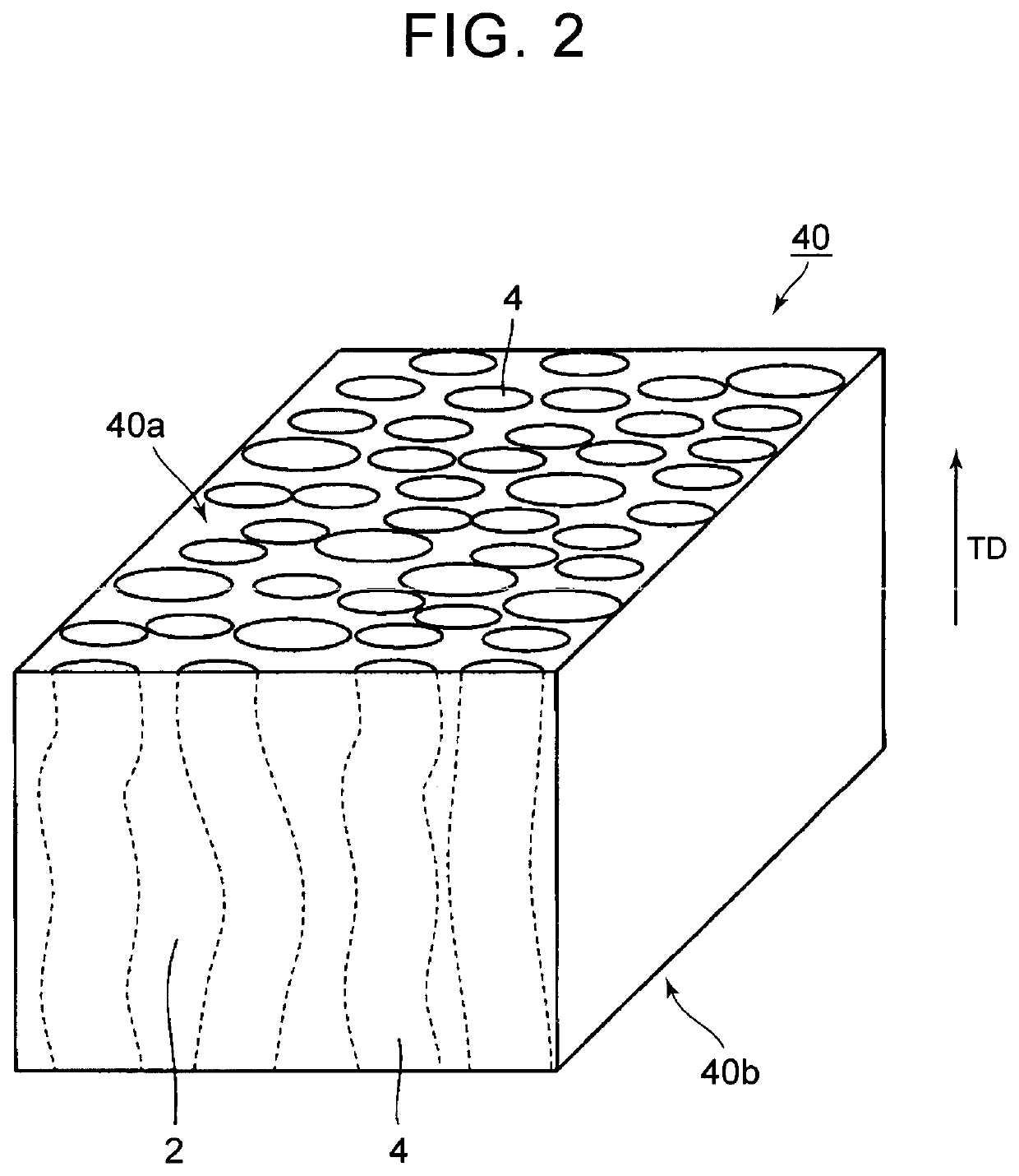
[0046]FIG. 2 is a schematic diagram showing a configuration example of major components of the separator 40 for a battery. Referring to FIG. 2, the separator 40 for a battery includes: plural resin fibers 4 by which the first main surface 40a and the second main surface 40b are connected; and pores 2 that are adjacent to the resin fibers 4. In the embodiment, a resin occupancy s, the thickness d of the separator, and a linearity index satisfy specific conditions. As a result, high input and output characteristics and safety are exhibited.

[0047][Cross-Sectional Analysis]

[0048]The resin occupancy s and the like can be obtaine...

second embodiment

or

[0077]A second embodiment relates to a laminated separator including the separator 40 for a battery. FIG. 5 is a schematic sectional view showing a configuration example of the laminated separator 45. Referring to FIG. 5, the laminated separator 45 has a structure in which a first layer 41, a second layer 42, and a third layer 43 are laminated in this order. In this example, the number of layers laminated is three. However, the number of layers laminated is not particularly limited as long as it is two or more. However, the number of layers laminated is preferably 5 or more in consideration of productivity and is most preferably 3 or more in consideration of the shape stability and the like.

[0078]In the laminated separator 45, at least one of the first layer 41, the second layer 42, and the third layer 43 is the separator 40 for a battery. In this case, the resin occupancy s of each layer is measured, and it is necessary that 0+ is determined in the layer having the highest resin ...

third embodiment

ndary Battery

[0093]A third embodiment relates to a lithium ion secondary battery. The lithium ion secondary battery includes the separator for a battery according to the first embodiment or the laminated separator according to the second embodiment. The lithium ion secondary battery exhibits superior input and output characteristics and safety based on the characteristics of the above-described separator for a battery and the like. Hereinafter, the lithium ion secondary battery will also be abbreviated as “single cell”.

[0094]FIG. 6 is a schematic diagram showing a configuration example of a lithium ion secondary battery according to the embodiment. Referring to FIG. 6, the single cell 100 is a sealed battery and includes a square case 50. The square case 50 includes: a case 52 that includes a pair of main surface walls 50a; and a lid 54. In the embodiment, the main surface walls 50a refer to side walls which face a flat portion 80a of a flat electrode body 80 described below among a...


PUM

PropertyMeasurementUnit
diameteraaaaaaaaaa
pressureaaaaaaaaaa
diameteraaaaaaaaaa

Abstract

Provided is a separator for a battery in which, when a ratio of a total length of line segments (Sa), in which an arbitrary straight line (La) intersects with resin fibers (4), to a total length of the straight line (La) on a cross-section of the separator in a thickness direction (TD) is represented by s (%) and when a thickness of the separator is represented by d (μm), 0<s≤100, 3≤d≤50, and 300≤d×s≤1500 are satisfied, the straight line (La) being parallel to a first main surface (40a) and crossing the cross-section.

Description

CROSS REFERENCE TO RELATED APPLICATIONS[0001]This application is a National Stage of International Application No. PCT / IB2015 / 001913 filed Oct. 16, 2015, claiming priority based on Japanese Patent Application No. 2014-212929 filed Oct. 17, 2014, the contents of all of which are incorporated herein by reference in their entirety.BACKGROUND OF THE INVENTION[0002]1. Field of the Invention[0003]The present invention relates to a separator for a battery, a laminated separator, a lithium ion secondary battery, and a battery pack.[0004]2. Description of Related Art[0005]Japanese Patent Application Publication No. 2006-236991 (JP 2006-236991 A) discloses a separator for a battery including: ultrafine fibers having a fiber diameter of 3 μm or less; and quasi-ultrafine modified cross-section fibers having a fiber diameter of 3 μm to 5 μm and a non-circular shape in cross-section.[0006]In many cases, a lithium ion secondary battery for a vehicle is used in the form of a battery pack in which p...

Claims


Application Information

Patent Timeline
Patent Type & Authority Patents(United States)
IPC IPC(8): H01M2/16H01M10/0525H01M10/0587H01M50/209H01M50/264H01M50/417H01M50/443H01M50/451H01M50/454H01M50/457H01M50/463H01M50/489
CPCH01M2/162H01M2/16H01M2/1606H01M10/0525H01M10/0587H01M50/44H01M50/463H01M50/489H01M50/417H01M50/209H01M50/451H01M50/443H01M50/264H01M50/457H01M50/454Y02E60/10Y02P70/50H01M50/446H01M50/411H01M50/449H01M50/20
Inventor UMEYAMA, HIROYASHIMAMURA, HARUNARI
Owner TOYOTA JIDOSHA KK
Why Eureka
Eureka Blog
Learn More