
Method and device for neural implant communication

a neural implant and communication technology, applied in the field can solve the problems of increasing complexity of implanted neural devices, and achieve the effects of improving the intuitiveness of the system for users, facilitating re-mapping of stimulus electrodes, and facilitating location mapping

Active Publication Date: 2021-02-16
SALUDA MEDICAL PTY LTD
View PDF362 Cites 23 Cited by
  • Summary
  • Abstract
  • Description
  • Claims
  • Application Information

AI Technical Summary

Benefits of technology

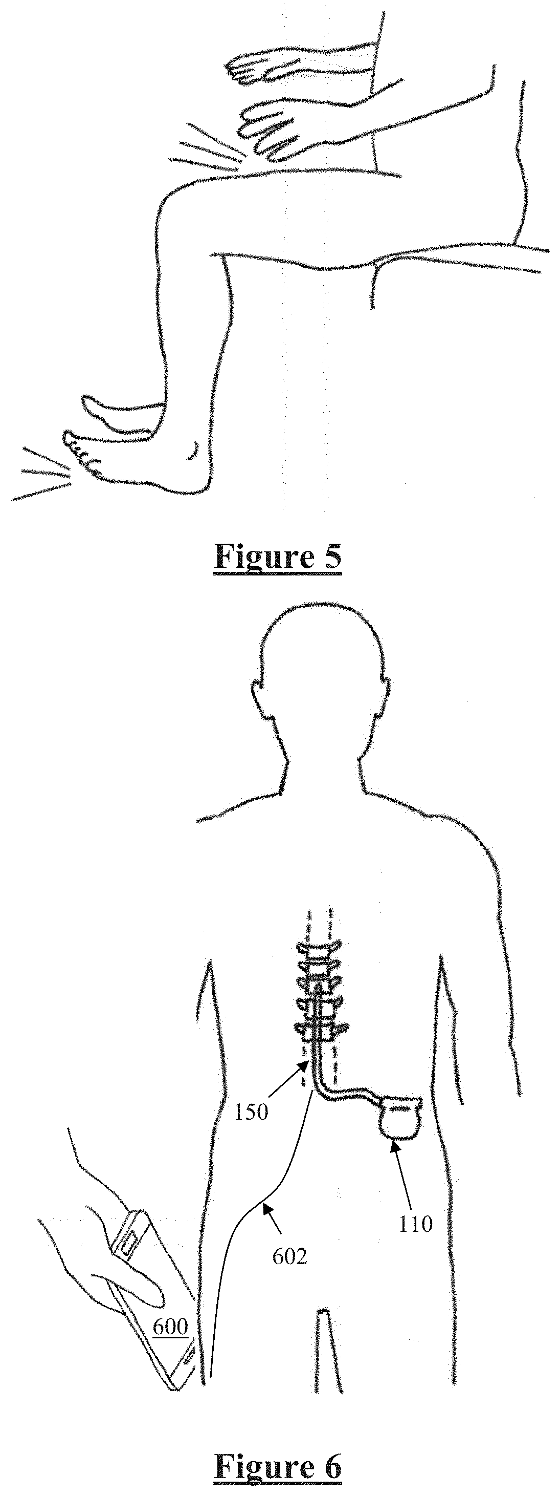
[0024]In some embodiments of the invention, the neural responses evoked for the purposes of communication are configured to be comfortable for the implant recipient. Indeed in some embodiments the neural responses evoked for the purposes of communication may be configured to be minimally perceptible or wholly imperceptible by the implant recipient. Such embodiments recognise that certain low levels of neural activity are not perceived by the brain but can be selectively evoked by a suitable stimulator and detected by a suitable receiver. Such embodiments may therefore be advantageous in avoiding the implant recipient perceiving any, or any significant, aberrant effects from communications stimuli. The perceptibility of the evoked communications responses may additionally or alternatively be minimised by using very short-time stimuli for communications purposes and / or delivering stimuli in an interleaved manner with therapeutic stimuli so that the communications stimuli are not perceived or at least are not unpleasant to the user. It is to be noted that where neural responses are evoked by motor activity such as the implant recipient activating a muscle, or by sensory input such as the user touching their leg, the neural responses thereby evoked are perceptible but not typically uncomfortable and may nevertheless be modulated in order to effect communications along the neural pathway.
[0027]In some embodiments the communications may originate from an external control device, and may be configured to control or alter the operation of an implanted device. For example the external control device may drive an input device such as a TENS device or a vibrational or haptic input device, to deliver encoded peripheral sensory stimuli which give rise to neural responses modulated with data which propagate along the afferent sensory nerves to the implanted device. Such embodiments may permit improved control of the duration, time and intensity of each stimulus, and thus may be particularly suited to delivery of higher data rates to the implanted device as compared to manual sensory input.
[0030]The encoding or modulation scheme used for manual sensory input communications is preferably configured to be distinguishable from normal motor activity, so that normal activity of the user is not undesirably detected as an instruction to change control settings of the implanted device. For example, motor or proprioceptive activity may be encoded by requiring consecutive motor actions or sensory inputs on one side of the body, so as to differentiate the encoded input from walking in which motor or proprioceptive activity occurs on alternating sides of the body. Formulating appropriate encoded sensory or motor input for a given implant recipient may be part of a fitting process after implantation of the implanted device. For example the user may have a preference of only tapping their feet to achieve such communications, or gently slapping their thighs, or the like. The user's preferred input activity may thus be accommodated during device fitting, in some embodiments. Moreover, the or each input pattern may resemble the rhythm of a favourite song or the like, to improve intuitiveness of the system for the user. In such embodiments the implanted device may thus be configured at the time of fitting to attach a unique control meaning to whichever input modulations are preferred by the user.
[0031]In further embodiments in which the communications originate from manual human input or a relocatable peripheral input such as a handheld TENS device, the implanted device may be configured to interpret such input as having occurred at a location at which paraesthesia is required. This may occur during a temporary re-mapping mode which may be entered when the implant recipient or a clinician wishes to redefine device parameters in order to change a region of paraesthesia delivered by the implanted device. When the device is in such a mode, an array of electrodes of the implanted device may detect neural responses on each electrode in a manner which corresponds to the indicated location of the required paraesthesia. The device may then reconfigure a stimulus pattern in a manner that optimises the stimuli delivered from each stimulus electrode, in a manner which optimally delivers paraesthesia to the location defined by the sensory input. Electrodes to sense the location being indicated by the manual sensory input may be positioned adjacent to one or more dorsal root ganglion in order to ease the location mapping to within the corresponding dermatome. A similar effect may be achieved by external device input such as by using an external haptic device to deliver sensory input at the location of required paraesthesia. Such embodiments may be particularly useful in cases of inaccurate electrode array implantation during surgery, or post-surgical lead migration, to facilitate re-mapping of stimulus electrodes.

Problems solved by technology

With the advent of high capacity implantable batteries and power-efficient processing, implanted neural devices are becoming increasingly complex and in particular numerous aspects of operation of an implanted neural device may be reconfigurable.

Method used


Image

  • Method and device for neural implant communication
  • Method and device for neural implant communication
  • Method and device for neural implant communication

Examples


Embodiment Construction

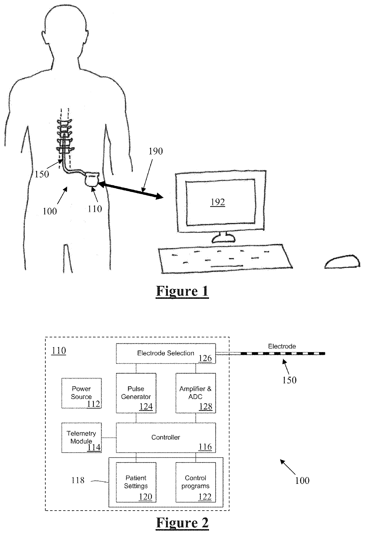
[0045]FIG. 1 schematically illustrates an implanted spinal cord stimulator 100. Stimulator 100 comprises an electronics module 110 implanted at a suitable location in the patient's lower abdominal area or posterior superior gluteal region, and an electrode assembly 150 implanted within the epidural space and connected to the module 110 by a suitable lead. Numerous aspects of operation of implanted neural device 100 are reconfigurable by an external control device 192. Moreover, implanted neural device 100 serves a data gathering role, and gathered data needs to be communicated to external device 192. These functions of implanted device 100 thus require the provision of a communications channel 190 from a controller 192 outside the body to the device 100 within the body.

[0046]FIG. 2 is a block diagram of the implanted neurostimulator 100. Module 110 contains a battery 112 and a telemetry module 114. In embodiments of the present invention, any suitable type of transcutaneous communic...


PUM


Abstract

Communications along a neural pathway are provided. The neural pathway is stimulated at a first location, in order to evoke neural responses which propagate along the neural pathway, the neural responses being modulated with data. At a second location spaced apart from the first location along the neural pathway the evoked neural responses are sensed. The sensed neural responses are then demodulated to retrieve the data. The stimulation could comprise peripheral sensory stimulation, and the second location could be at an implanted electrode array.

Description

TECHNICAL FIELD[0001]The present invention relates to implanted neural devices, being devices which are able to evoke and / or sense neural activity upon a neural pathway, and in particular to a method and system for establishing communication with such devices.BACKGROUND OF THE INVENTION[0002]A range of implanted neural devices exist, including: spinal cord implants which electrically stimulate the spinal column in order to suppress chronic pain; cochlear implants which electrically stimulate the auditory nerve to produce a hearing sensation; deep brain stimulators which electrically stimulate selected regions of the brain to treat conditions such as Parkinson's disease or epilepsy; and neural bypass devices which electrically stimulate either afferent sensory nerve fibres to reproduce impaired sensory function or efferent motor nerve fibres to reproduce impaired motor activity, or both.[0003]With the advent of high capacity implantable batteries and power-efficient processing, impla...

Claims


Application Information

Patent Timeline
Patent Type & Authority Patents(United States)
IPC IPC(8): A61N1/372A61B5/00A61B5/04A61N1/36A61N1/05G06F3/01
CPCA61N1/37217A61B5/0028A61B5/0031A61B5/04001A61B5/686A61B5/7475A61N1/36132G06F3/015A61B2560/0487A61N1/0526A61N1/37211A61B5/24A61B5/388
Inventor PARKER, JOHN LOUISSTAPLES, MARK
Owner SALUDA MEDICAL PTY LTD
Learn More