Compact optical system for a motor-vehicle passenger compartment
a passenger compartment and compact technology, applied in the field of automobile industry, can solve the problems of reducing the comfort of users of motor vehicles, incompatibility of pixelated light sources, and scarce housing available in passenger compartments, and achieve the effect of reducing the bulk of such optical systems
- Summary
- Abstract
- Description
- Claims
- Application Information
AI Technical Summary
Benefits of technology
Problems solved by technology
Method used
Image
Examples
first embodiment
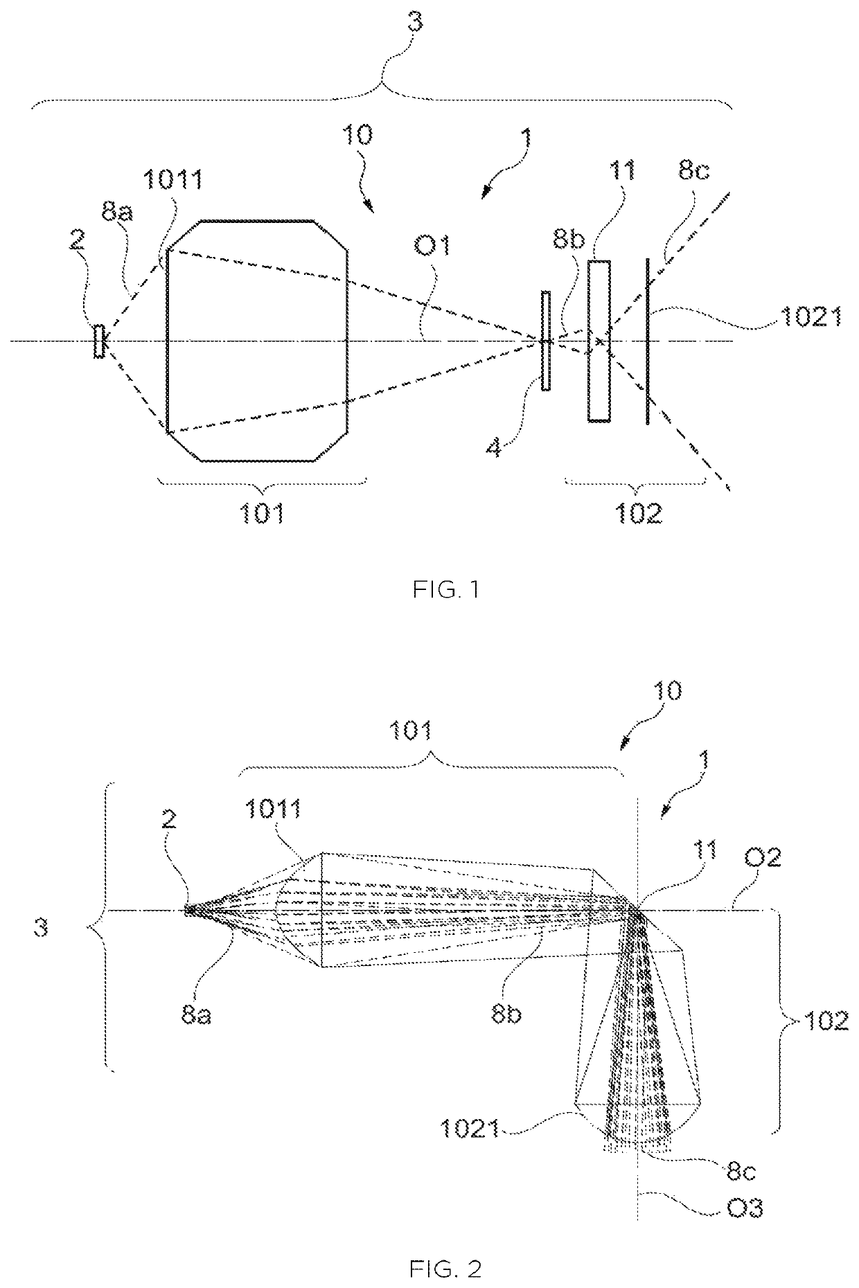
[0062]FIG. 1 illustrates a schematic version of the optical system 1 implemented in an interior lighting device 3, and in which the optical system 1 lies on a single optical axis O1.
[0063]The first portion 101 of the optical assembly 10 is located at distance from the light source 2 and possesses a large admission angle, so that most—and preferably all—of the light rays 8a generated by the light source 2 penetrate into the optical system 10 through the entrance face 1011 of the first portion 101 of the optical assembly 10. The first portion 101 is formed by one or more lenses and / or by one or more reflective surfaces, in order to form the real image 4 of the light source 2 in a position that is optically intermediate between the first portion 101 and the diffuser 11, along the single optical axis O1.
[0064]All of the incident light rays 8b that reach the diffuser 11 beyond the real image 4 of the light source 2 together form a cone an opening angle of which is smaller than that of a ...
second embodiment
[0068]FIG. 2 illustrates a schematic version of the optical system 1 implemented in an interior lighting device 3, and wherein the optical system 1 has a dog-legged configuration.
[0069]The first portion 101 of the optical assembly 10 is located at distance from the light source 2 and possesses a large admission angle, so that most—and preferably all—of the light rays 8a generated by the light source 2 penetrate into the optical system 10 through the entrance face 1011 of the first portion 101 of the optical assembly 10. The first portion 101 is formed by one or more lenses and / or by one or more reflective surfaces in order to form the real image of the light source 2 at the diffuser 11, along a first optical axis O2 that extends in a first direction.
[0070]The diffuser 11 of the optical system 10 illustrated in FIG. 2 is reflective and it is oriented with respect to the first optical axis O2 so as to make a nonzero angle that is preferably comprised between 20° and 70°. In order to m...
third embodiment
[0086]The optical system illustrated in this third embodiment is particularly compact and economical to manufacture, because it results from the assembly of the two optical parts 101A, 101B and from their combination with the second portion 102 of the optical assembly 10.
[0087]In summary, the invention in particular relates to an optical system 1 and to an interior motor-vehicle lighting device 3 comprising a light source 2 coupled to such an optical system 1. The optical system 1 comprises a first portion 101 of an optical assembly 10 that allows a real image 4 of the light source 2 to be projected into proximity to a diffuser 11 of the optical system 1. The optical assembly 10 of the optical system 1 also comprises a second portion 102 that plays the role of a projecting optic in order to project, out of said optical system 1, a real image of the real image of the light source 2 formed in proximity to the diffuser 11. The optical system 1 according to the invention allows a lumina...
PUM
| Property | Measurement | Unit |
|---|---|---|
| angle | aaaaa | aaaaa |
| angle | aaaaa | aaaaa |
| angle | aaaaa | aaaaa |
Abstract
Description
Claims
Application Information
 - R&D
- Intellectual Property
- Life Sciences
- Materials
- Tech Scout
- Unparalleled Data Quality
- Higher Quality Content
- 60% Fewer Hallucinations
Browse by: Latest US Patents, China's latest patents, Technical Efficacy Thesaurus, Application Domain, Technology Topic, Popular Technical Reports.
© 2025 PatSnap. All rights reserved.Legal|Privacy policy|Modern Slavery Act Transparency Statement|Sitemap|About US| Contact US: help@patsnap.com


