
Battery control unit

a battery cell and control unit technology, applied in the direction of indicating/monitoring circuits, instruments, transportation and packaging, etc., can solve the problems of inability to consider the change in resistance value over time, large errors in detected voltage, and time-consuming to detect the voltage of battery cells. , to achieve the effect of accurate and timely detection of battery cell voltag

Active Publication Date: 2021-01-26
DENSO CORP
View PDF11 Cites 1 Cited by
  • Summary
  • Abstract
  • Description
  • Claims
  • Application Information

AI Technical Summary

Benefits of technology

The present invention provides a battery control apparatus capable of accurately and quickly detecting the voltage of battery cells. The apparatus includes a battery control unit with voltage detection units for each battery cell, a connection member, a discharge circuit and a correction value calculation unit. The correction value calculation unit calculates the voltage drop at the connection member when discharging the battery cells through the discharge circuit. This correction value is then added to the post-discharge voltage to calculate the voltage of the battery cell. This technology allows for improved battery control and management.

Problems solved by technology

Hence, this is one of causes of the detection error when the voltage detection circuit detects voltages.
However, according to a technique disclosed by the above-mentioned patent literature, since a correction value is determined in the design phase, a change in the resistance value over time cannot be considered.
Therefore, according to a correction technique disclosed in the above-mentioned patent literature, errors in the detected voltage become large.
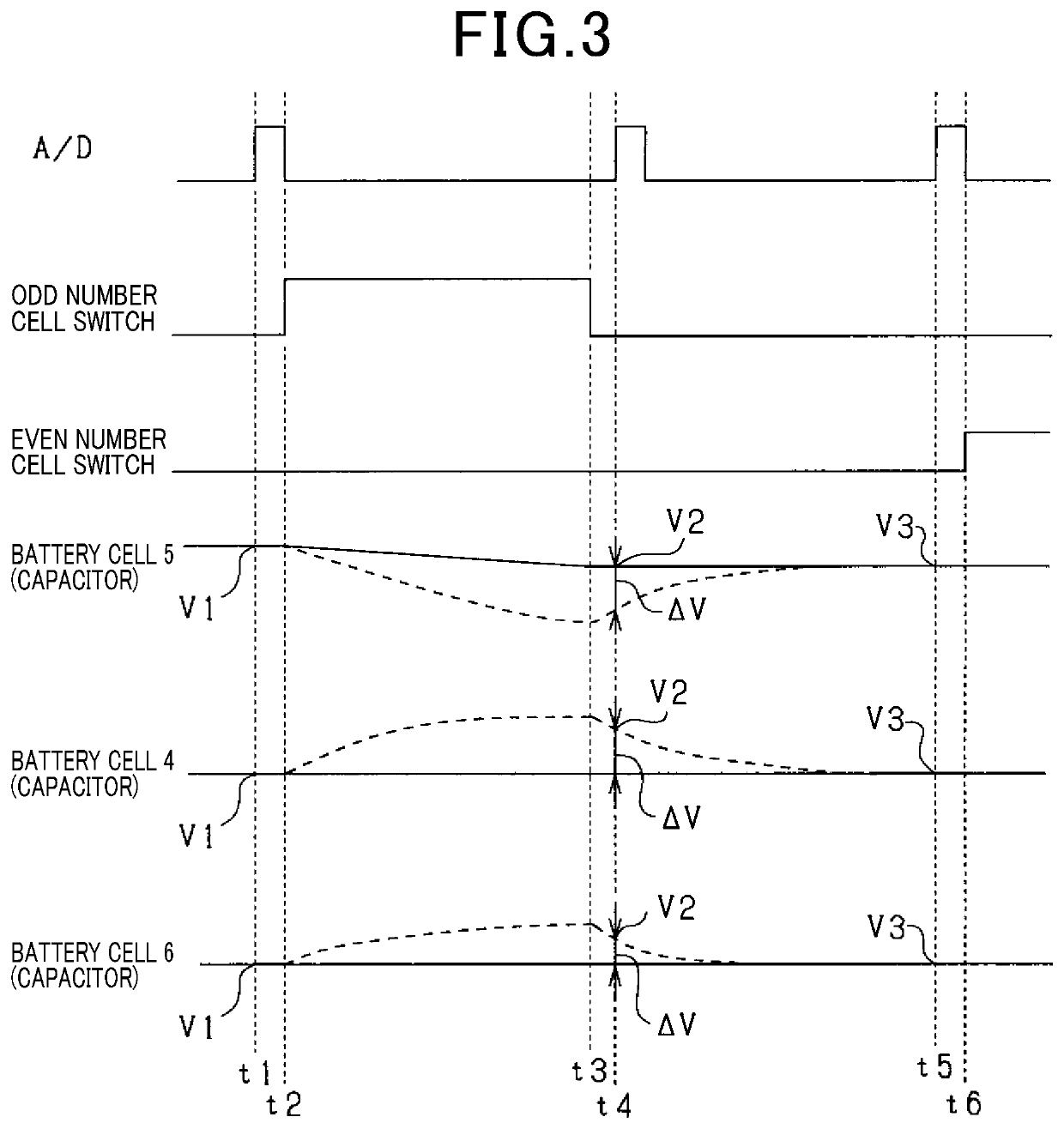
However, if the time constant of the low pass filter is large, it takes time until the influence of the discharging on the capacitor disappears.
This is the cause of error included in the voltage detected at the voltage detection unit.
Further, since the resistance changes over time due to aging or the like, it is difficult to calculate in advance a difference between the capacitor voltage at the capacitor after discharging and the battery cell voltage, that is, an amount of voltage drop at the connection member.

Method used


Image

  • Battery control unit
  • Battery control unit
  • Battery control unit

Examples


Embodiment Construction

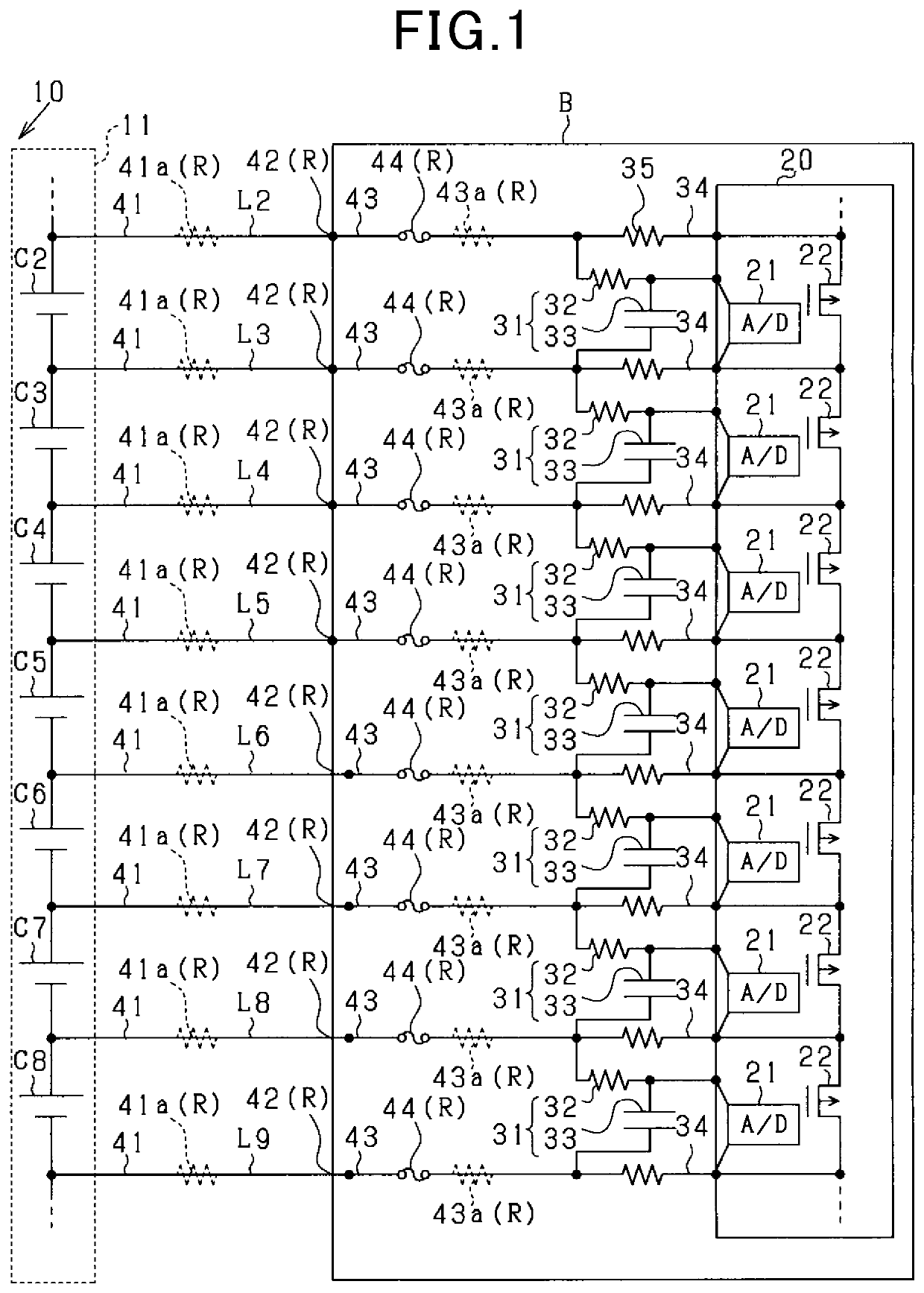
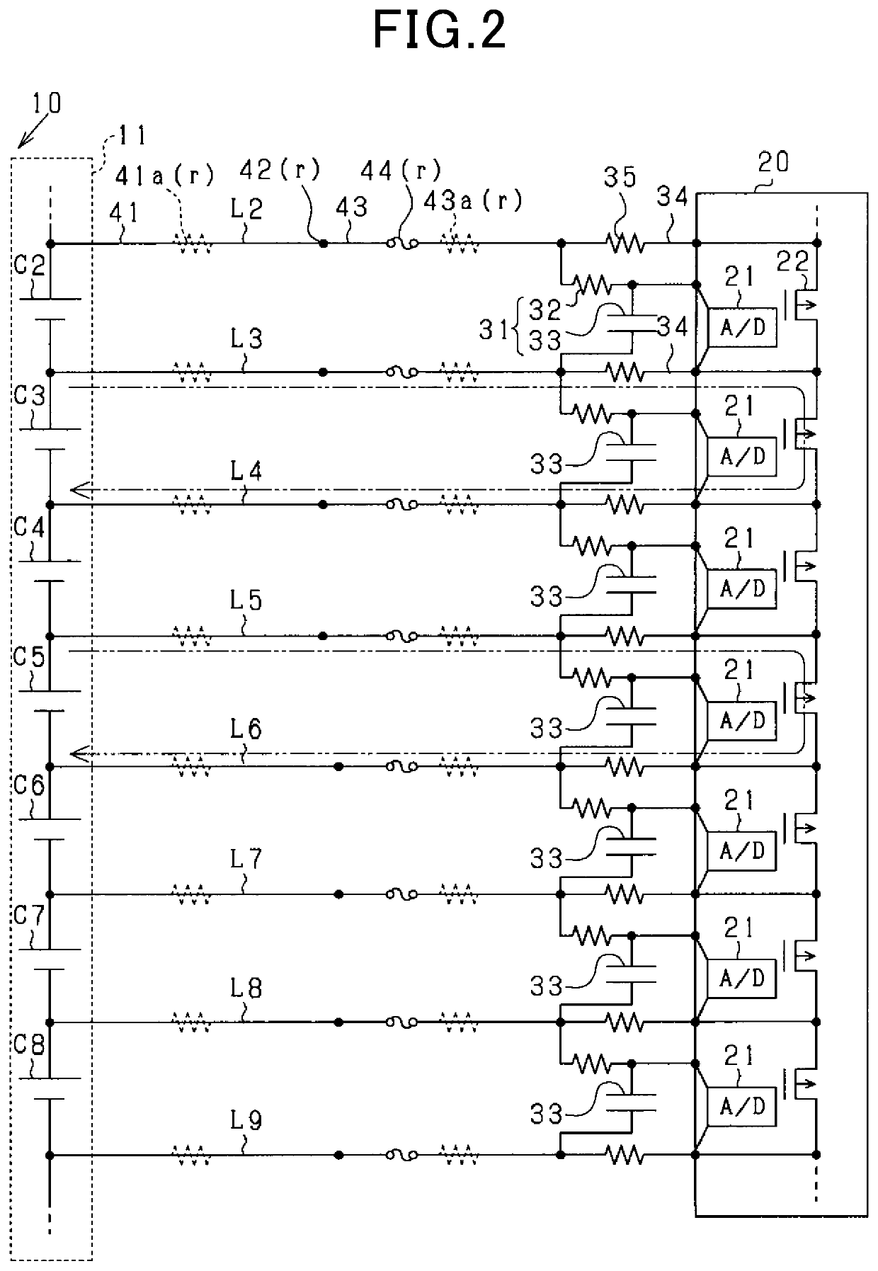
[0030]With reference to drawings, embodiments of a battery control unit according to the present disclosure will be described. The battery control unit according to the present disclosure is adapted for power supply systems mounted on hybrid vehicles or electric vehicles, for example.

[0031]As shown in FIG. 1, the power supply system is provided with a storage battery 10. The storage battery 10 is configured of, for example, a lithium ion battery serving as a power source for on-vehicle electrical load including a traction motor (not shown) of a vehicle. Note that it is not limited to lithium ion batteries, but other types of batteries such as nickel hydride batteries may be used as long as a storage battery composed of a plurality of battery cells which supplies a predetermined voltage is used.

[0032]The storage battery 10 is composed of a battery module 11 including n battery cells C1-Cn connected in series, where n is an integer one or more, approximately several to several tens. T...


PUM


Abstract

A battery control unit is adapted for a power supply system provided with a storage battery series-connected battery cells, a filter circuit, a discharge circuit, and a connection member connecting between the battery cell and the filter circuit.The battery control unit includes a voltage detection unit detecting voltage at the battery cell where noise is eliminated by the filter circuit, the voltage being detected immediately before / after a discharging is performed through the discharge circuit; a correction value calculation unit that calculates an amount of a voltage drop at the connection member when a discharging is performed through the discharge circuit, to be a correction value; and a voltage calculation unit that calculates voltage of the battery cell by adding the correction value calculated by the correction value calculation unit to a post-discharge voltage detected immediately after the discharging by the voltage detection unit.

Description

CROSS-REFERENCE TO RELATED APPLICATION[0001]This application is based on and claims the benefit of priority from earlier Japanese Patent Application No. 2017-236261 filed Dec. 8, 2017, the description of which is incorporated herein by reference.BACKGROUNDTechnical Field[0002]The present disclosure relates to a battery control unit.Description of the Related Art[0003]A power supply system provided with a storage battery in which a plurality of battery cells are connected in series includes a voltage detection circuit for detecting voltages of the battery cells, an equalization circuit for equalizing the voltages of the battery cells detected by the voltage detection circuit. A low pass filter is provided between the voltage detection circuit and each battery cell so as to eliminate noise included in the voltage transmitted to the voltage detection circuit from each battery cell. By measuring the capacitor voltage of the low pass filter circuit, the voltage of each battery cell is de...

Claims


Application Information

Patent Timeline
Patent Type & Authority Patents(United States)
IPC IPC(8): G01R31/396H02J7/00G01R31/3835
CPCH02J7/0021G01R31/3835G01R31/396H02J7/0016G01R31/374H02J7/0047
Inventor KITAGAWA, MASAAKIITO, MASAHIKOKOUDA, MASAKAZUISHIBE, ISAO
Owner DENSO CORP
Learn More