
Light fixture for repair tools

a technology for repair tools and light fixtures, applied in semiconductor devices, lighting and heating apparatuses, power sources, etc., can solve the problems of poor light focusing effect, easy breakage, and difficult disassembly of installed lighting devices, and achieve good light focusing effect, convenient disassembly and assembly, and convenient disassembly.

Active Publication Date: 2021-01-26
TAIZHOU BESWELL MACHINERY
View PDF13 Cites 0 Cited by
  • Summary
  • Abstract
  • Description
  • Claims
  • Application Information

AI Technical Summary

Benefits of technology

The patent describes a light fixture that is made from reinforced plastic and has a unique design. The fixture is resistant to vibration and has good light focusing capabilities. The device can be recharged many times and is easy to use and repair. The edge of the housing is made using bicomponent casting technology, which ensures the device is durable. Additionally, the notches on both sides have an anti-slip design to prevent any slipping or catching of objects. Overall, the patent describes a light fixture that is comfortable, durable, and efficient.

Problems solved by technology

Existing manual, pneumatic and hydraulic tools do not have lighting devices, so when performing work in fairly cloudy weather or at night, one has to resort to the use of additional lighting devices.
In some power tools, even those with lighting devices, the focusing of light is poor, in certain circumstances, for example, in a narrow space.
Further, the installed lighting devices are not easy to disassemble, and they can easily break if exposed to vibration.
If such a device breaks, it will be necessary to repair and inspect the entire circuit.
No effective solution to this issue has been found at present.

Method used


Image

  • Light fixture for repair tools
  • Light fixture for repair tools
  • Light fixture for repair tools

Examples


Embodiment Construction

[0022]The drawings show an example of implementation of this design. This example provides a clear, integral description of the technical solution for implementing this design. Obviously, the described implementation example is only a partial implementation of the design, and not its full implementation. According to this example of implementation of the design, all other implementation examples obtained by normal technical personnel in this field depend on the protection area of this design.

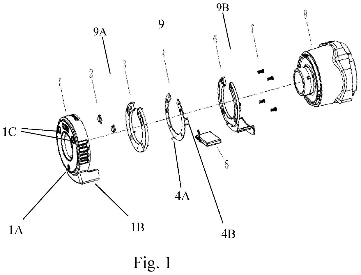
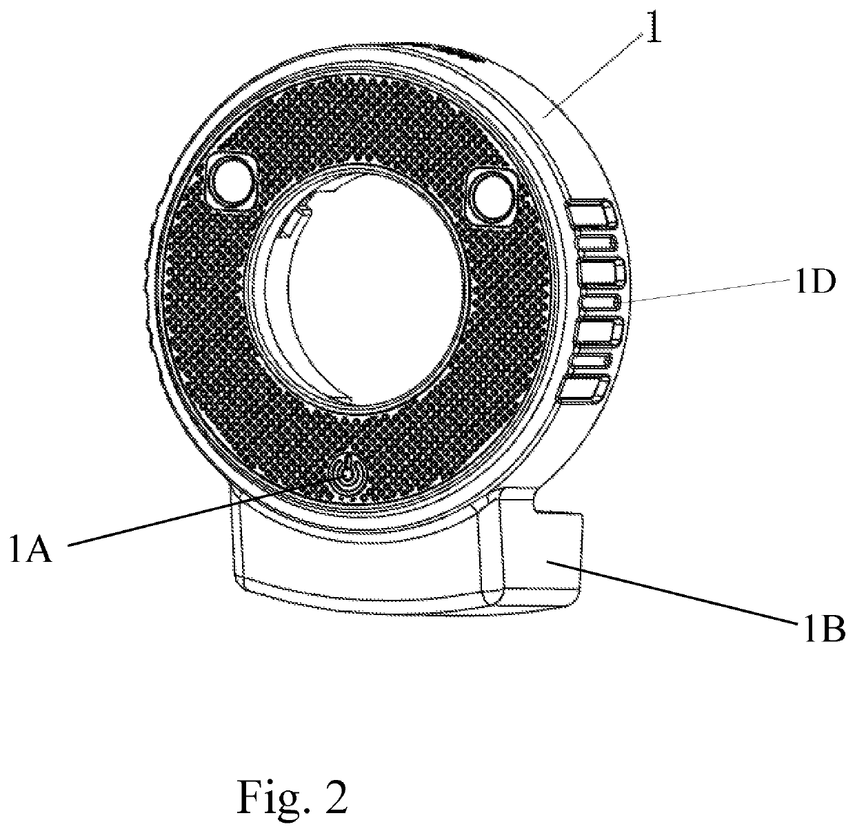
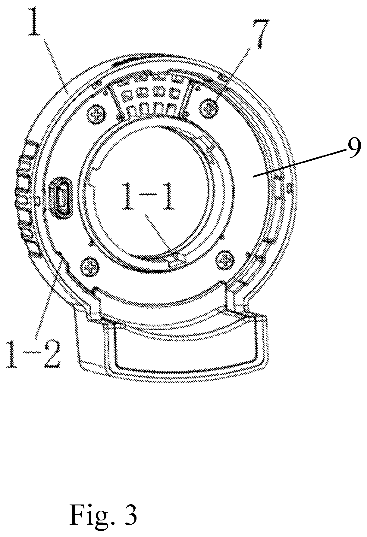
[0023]As shown in FIG. 1, the light fixture for repair tools includes a round housing 1, in the bottom of the housing 1 there is a battery compartment 1i, and in the center of the housing 1 there is an opening. There are two light source openings 1C on the front face of the housing 1 that are on opposite sides of the opening in the housing 1. On the inside of the housing 1 there is a mount for the mounting plate mount, and an LED mounting plate 4 is installed into the mounting plate mount. On th...


PUM


Abstract

A light fixture for repair tools that includes a housing, a battery compartment in the lower part of the housing, a hole in the center of the housing, two light source openings on both sides of this hole, a mount for a mounting plate on the inside of the housing, and an LED mounting plate built into this mount. Two LEDs are located on this plate, compatible with the above light source openings, and at the bottom of the LED mounting plate there is a sensor switch. Lightweight reinforced plastic is used for the light fixture, the edge of the housing is made using bicomponent casting technology, and the notches on both sides have an anti-slip design. The housing allows achievement of a good light focusing effect, the fixtures are resistant to vibration and loosening, the battery can be repeatedly recharged, and the device is convenient to use and repair.

Description

FIELD OF THE INVENTION[0001]This disclosure relates to the technical field of lighting devices, in particular, to the field of light fixtures for repair tools.BACKGROUND OF THE INVENTION[0002]Currently, repair tools (manual, electric, pneumatic, hydraulic) are widely used in various fields, and lighting devices are a necessary element when working with a repair tool. Lighting devices are used to improve working conditions, contribute to better monitoring and control of the work process, facilitate work of technical personnel and ensure the safety and stability of repair work.[0003]Existing manual, pneumatic and hydraulic tools do not have lighting devices, so when performing work in fairly cloudy weather or at night, one has to resort to the use of additional lighting devices. In some power tools, even those with lighting devices, the focusing of light is poor, in certain circumstances, for example, in a narrow space. Further, the installed lighting devices are not easy to disassemb...

Claims


Application Information

Patent Timeline
Patent Type & Authority Patents(United States)
IPC IPC(8): F21V33/00F21S9/02F21V5/00F21V23/04F21Y115/10
CPCF21V33/0084F21S9/02F21V5/007F21V23/0442F21Y2115/10
Inventor LEE, NILE
Owner TAIZHOU BESWELL MACHINERY
Learn More