Multi-spatial mode enabled PAT and AO terminal architecture for free-space optical communications

a terminal architecture and free-space technology, applied in multiplex communication, line-of-sight transmission, wavelength-division multiplex systems, etc., can solve the problems of reducing the complexity affecting the efficiency of the overall system, and difficult to couple light into a single-mode fiber, etc., to achieve a wider acceptance angle, reduce the effect of complexity and large effective core area

Active Publication Date: 2021-01-12
MASSACHUSETTS INST OF TECH
View PDF15 Cites 3 Cited by
  • Summary
  • Abstract
  • Description
  • Claims
  • Application Information

AI Technical Summary

Benefits of technology

[0008]Fortunately, photonic lanterns may alleviate some of the difficulties associated with conventional PAT system. To start, it is easier to couple light into the multi-mode input of a photonic lantern than into a single-mode fiber because the photonic lantern's multi-mode input has a larger effective core area, which results in a wider acceptance angle and lower insertion loss. The photonic lantern passively transforms each spatial mode coupled into the multi-mode input into separate single-mode outputs. In other words, the photonic lantern efficiently and repeatably maps energy from the spatial mode distribution at the multi-mode input to the single-mode outputs. These single-mode outputs can be detected coherently or incoherently and used for communications and fine tracking simultaneously.
[0009]Using a passive mode demultiplexer, such as a photonic lantern, mode converter, or Cailabs multi-plane light conversion device, to couple light into many single-mode fibers allows an optical terminal to determine tilt angle for fine tracking without diverting any power from the communication receiver path. As a result, it is possible to use energy detected from different spatial modes for both communication and tilt angle tracking, which is beneficial when the received signal power is low. For low data rate links, this is especially beneficial because it allows all of the energy to be used for communications thus avoiding situations in which some or most of the energy is used for PAT, as can happen with a conventional PAT system.
[0010]A passive mode demultiplexer (e.g., a photonic lantern) also increases the field-of-view (FOV) of the optical coupling elements by employing multi-spatial mode coupling. The increase in FOV of the optical coupling elements has a direct impact on optical terminal design by moving PAT system complexity from the optical head to backend digital signal processing (DSP). The backend DSP can implement combining of signals detected behind each spatial mode, which is also a digital implementation of adaptive optical (AO) compensation. Moving PAT complexity from the optical head to backend DSP potentially reduces overall system complexity.

Problems solved by technology

Unfortunately, coupling light into a single-mode fiber is difficult and often inefficient, especially if a portion of the signal is tapped off for PAT instead of being used for communications.
Moving PAT complexity from the optical head to backend DSP potentially reduces overall system complexity.

Method used


Image

  • Multi-spatial mode enabled PAT and AO terminal architecture for free-space optical communications
  • Multi-spatial mode enabled PAT and AO terminal architecture for free-space optical communications
  • Multi-spatial mode enabled PAT and AO terminal architecture for free-space optical communications

Examples


Embodiment Construction

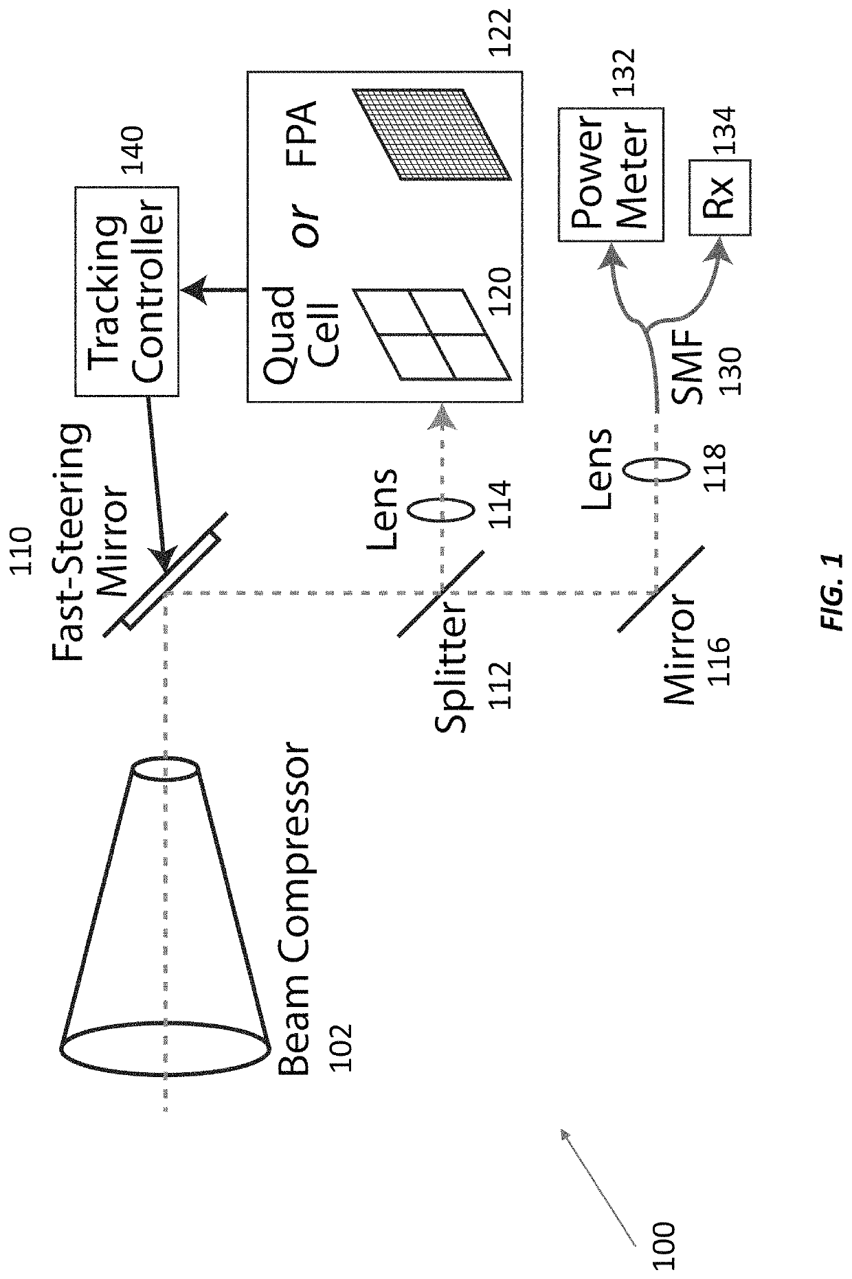
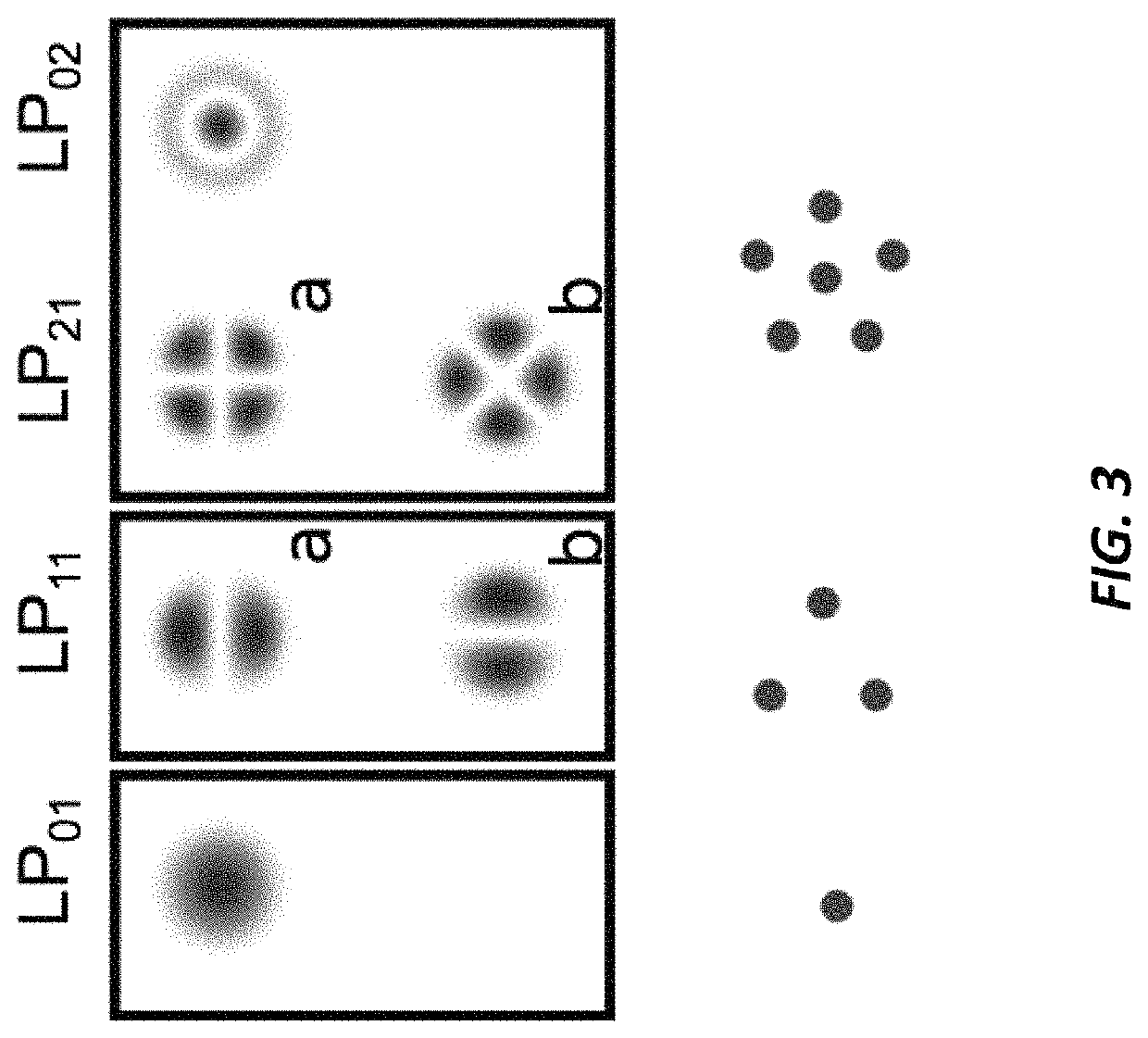
[0032]Multi-spatial mode pointing, acquisition, and tracking (PAT) technology can be used for determining tilt angle of an incident free-space optical communications beam without diverting energy from the communications receiver. In particular, the spatial tracking information in the focal plane can be determined by the relative amount of signal detected in different spatial modes. In this way, it becomes possible to increase or maximize the received energy for communications while simultaneously detecting tilt angle. There are multiple ways in which multiple spatial modes can be used to determine tilt angle information.

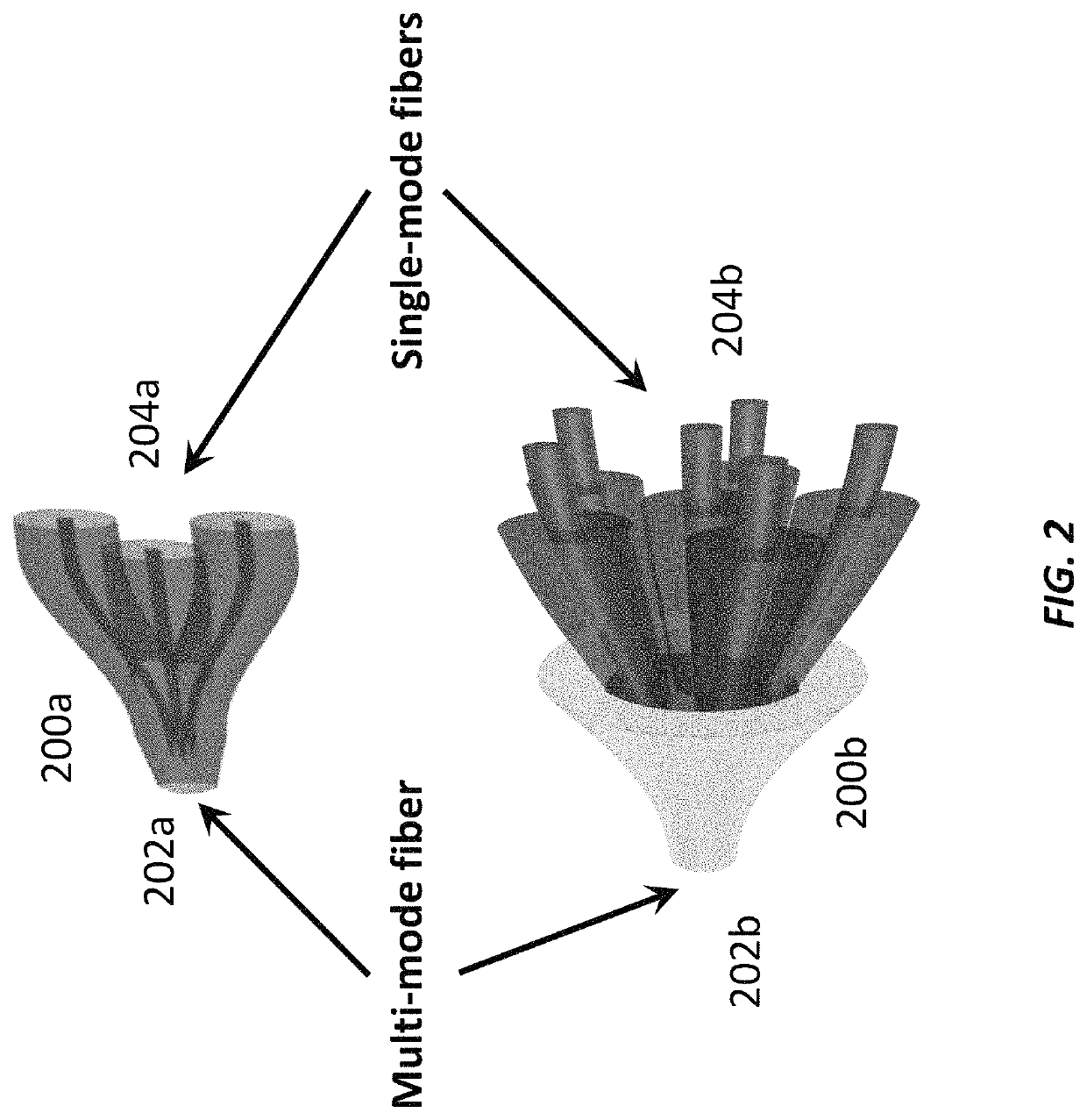
[0033]One technique involves coupling light from a receive aperture to a multi-mode fiber (MMF) or few-mode fiber (FMF). The light energy in the MMF or FMF is then separated into several single-mode fiber (SMF) outputs using a passive MMF-to-SMF or FMF-to-SMF convertor that has one SMF output for each spatial mode in the MMF or FMF. A passive spatial mode convertor c...


PUM


Abstract

Many free-space optical (FSO) communications systems use pointing, acquisition, and tracking (PAT) systems to align the transmit and receive apertures for efficiently coupling received light to a detector. Conventional PAT systems divert energy from the communications receiver to a photodiode array for measuring tilt in the focal plane. Unfortunately, diverting energy from communications to PAT reduces SNR and sensitivity for communications. The PAT terminal disclosed here determines tilt angle without diverting energy from the communications receiver. It tracks the power in different spatial modes and uses that power distribution to determine tilt information for PAT. It does this with a passive mode converter, such as a photonic lantern, that maps power in each spatial mode at the receive aperture to a different single-mode output. Photodetectors at the single-mode outputs convert the received light into electrical signals that are demodulated for communications and whose amplitudes are used to derive the tilt information.

Description

CROSS-REFERENCE TO RELATED APPLICATION[0001]This application claims the priority benefit, under 35 U.S.C. § 119(e), of U.S. Application No. 62 / 839,956, filed on Apr. 29, 2019, which is incorporated herein by reference in its entirety.GOVERNMENT SUPPORT[0002]This invention was made with Government support under Grant No. FA8702-15-D-0001 awarded by the U.S. Air Force. The Government has certain rights in the invention.BACKGROUND[0003]Many free-space optical (FSO) communications systems require acquisition, pointing, and tracking (PAT) systems to align the transmit and receive telescope apertures to efficiently couple the received light to a detector or to optical fiber for subsequent detection. In particular, a PAT system should determine (and correct) the tilt angle error of a signal incident on an optical receive aperture. A conventional PAT system diverts energy from the communications receiver optical path and uses a lens followed by a photodiode array (e.g., quadrant detector ph...

Claims


Application Information

Patent Timeline
Patent Type & Authority Patents(United States)
IPC IPC(8): H04B10/112H04J14/02
CPCH04B10/1127H04J14/0221H04B10/112H04J14/04
Inventor GEISLER, DAVID JYARNALL, TIMOTHY M
Owner MASSACHUSETTS INST OF TECH
Why Eureka
Try Eureka