Deployable disk antenna

a technology of deployable antennas and disks, applied in the direction of collapsable antennas, antenna earthings, radiating element structural forms, etc., can solve the problems of difficult to facilitate high gain, difficult to provide high-gain deployable antennas, and inefficient helix operation for length

Undetermined Publication Date: 2021-01-12
EAGLE TECH LLC
View PDF12 Cites 4 Cited by
  • Summary
  • Abstract
  • Description
  • Claims
  • Application Information

AI Technical Summary

Benefits of technology

[0008]According to one aspect, a spacing between adjacent ones of the electrically active plates when the mast is in the second condition is 0.2λ, where λ is a wavelength of a design frequency at which the disk antenna is to operate. Further, the ground plane plate may be comprised of two conductive ground plane layers, spaced apart by a predetermined distance by one or more inner conductive elements which electrically connect the two or more conductive ground plane layers to define an RF trap.
[0009]The mast is comprised of one or more elements selected from the group consisting of a spoolable extensible member (SEM), and a plurality of telescoping sections. The one or more suspension members are flexible tensile members secured at a first end to a carrier plate disposed at a radiating end of the mast, distal from the ground plate. The one or more flexible tensile members are configured to determine the plurality of distributed locations of the plates when the mast is in the second condition.
[0010]In some scenarios, one or more of the ground plane plate, the plurality of electrically active plates, and the drive plate include a principal aperture through which the mast extends when the mast is in the second condition. In such scenarios, one or more of the ground plane plate, the plurality of electrically active plates, and the drive plate may be conductively isolated from the mast or may be conductively coupled to the mast.
[0011]The invention also concerns a method for deploying a disk antenna. The method involves arranging a plurality of plates to form a stack aligned along a principal axis, where each plate comprises a major conductive surface extending in directions transverse to the principal axis. The method also involves arranging the plurality of plates in the stack to include a drive plate disposed between a ground plane plate and a plurality of electrically active plates. The method can continue by controlling deployment of the disk antenna. Such deployment can involve transitioning a mast from a first condition in which the mast is compactly stowed, to a second condition in which a length of the mast along the principal axis is increased as compared to the first condition. One or more suspension members which are directly or indirectly coupled to the mast, are then used to urge the plurality of electrically active plates, in response to the transitioning. This step involves urging the electrically active plates from a stowed configuration in which the plates are compactly stacked, to a deployed configuration in which a spacing between adjacent ones of the electrically active plates is increased. Consequently, the electrically active plates are distributed at predetermined spaced apart locations along an elongated length of the mast in the second condition.

Problems solved by technology

Such high gain can be challenging to facilitate when the size of the antenna is constrained.
Providing a high-gain deployable antenna as described herein can become even more challenging when operating in the UHF frequency range.
Still, such a space deployable helix has some unwanted shortcomings: 1) the elastic nature of the spring may result in un-damped motions for which spacecraft reaction wheels must contend; 2) lower frequency helical spring elements may be costly to fabricate as they essentially comprise a relatively large relaxed spring that must be furnace tempered; 3) the traveling wave mode of helix operation is not efficient in gain for length performance compared to Brown Woodward theoretical gain length limits; 4) the axial velocity component of current along a constant winding pitch helix may have difficulty matching the axial velocity of the advancing wave; 5) a single helix cannot provide simultaneous dual polarizations 6) the single axial mode helix is undesirable for linear polarization; and 7) the helix has a driving point resistance near 130 ohms requiring matching.
Yet in space the parabola presents deployment risks.
These risks are due to the overall complexity of the structure, the behavior of lubricants in space (which are complex), the presence of many moving parts, re-radiation of passive intermodulation, and costs associated with parabola.
So, while helix antennas and parabola reflector antennas have sometimes been used to facilitate the need for deployable antenna systems, their challenges are many.
Further, these antenna designs can be inadequate to provide the necessary amount of gain—particularly under conditions where the physical size of the antenna is constrained by a particular set of design requirements.

Method used


Image

  • Deployable disk antenna
  • Deployable disk antenna
  • Deployable disk antenna

Examples


Embodiment Construction

[0025]It will be readily understood that the solution described herein and illustrated in the appended figures could involve a wide variety of different configurations. Thus, the following more detailed description, as represented in the figures, is not intended to limit the scope of the present disclosure, but is merely representative of certain implementations in various different scenarios. While the various aspects are presented in the drawings, the drawings are not necessarily drawn to scale unless specifically indicated.

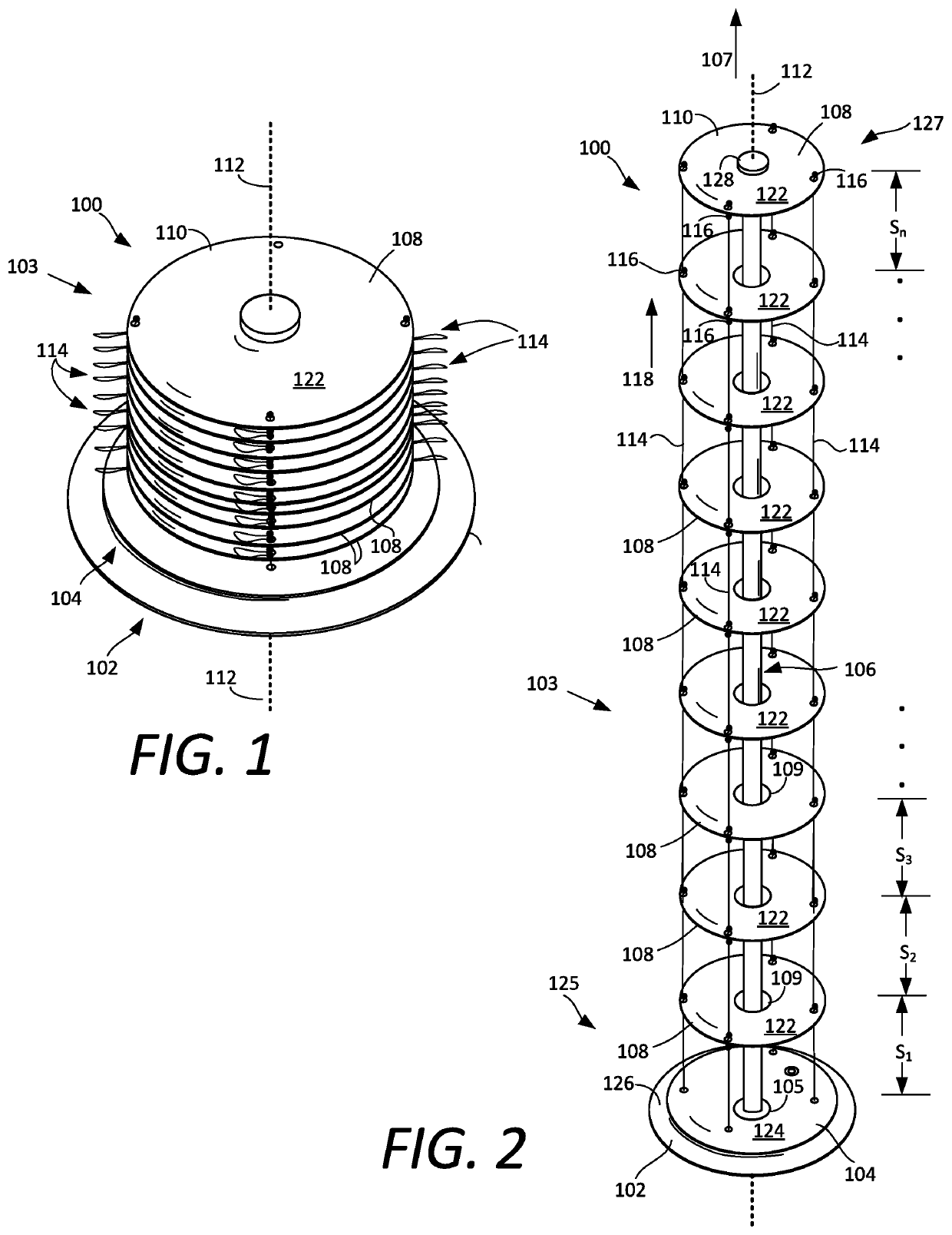
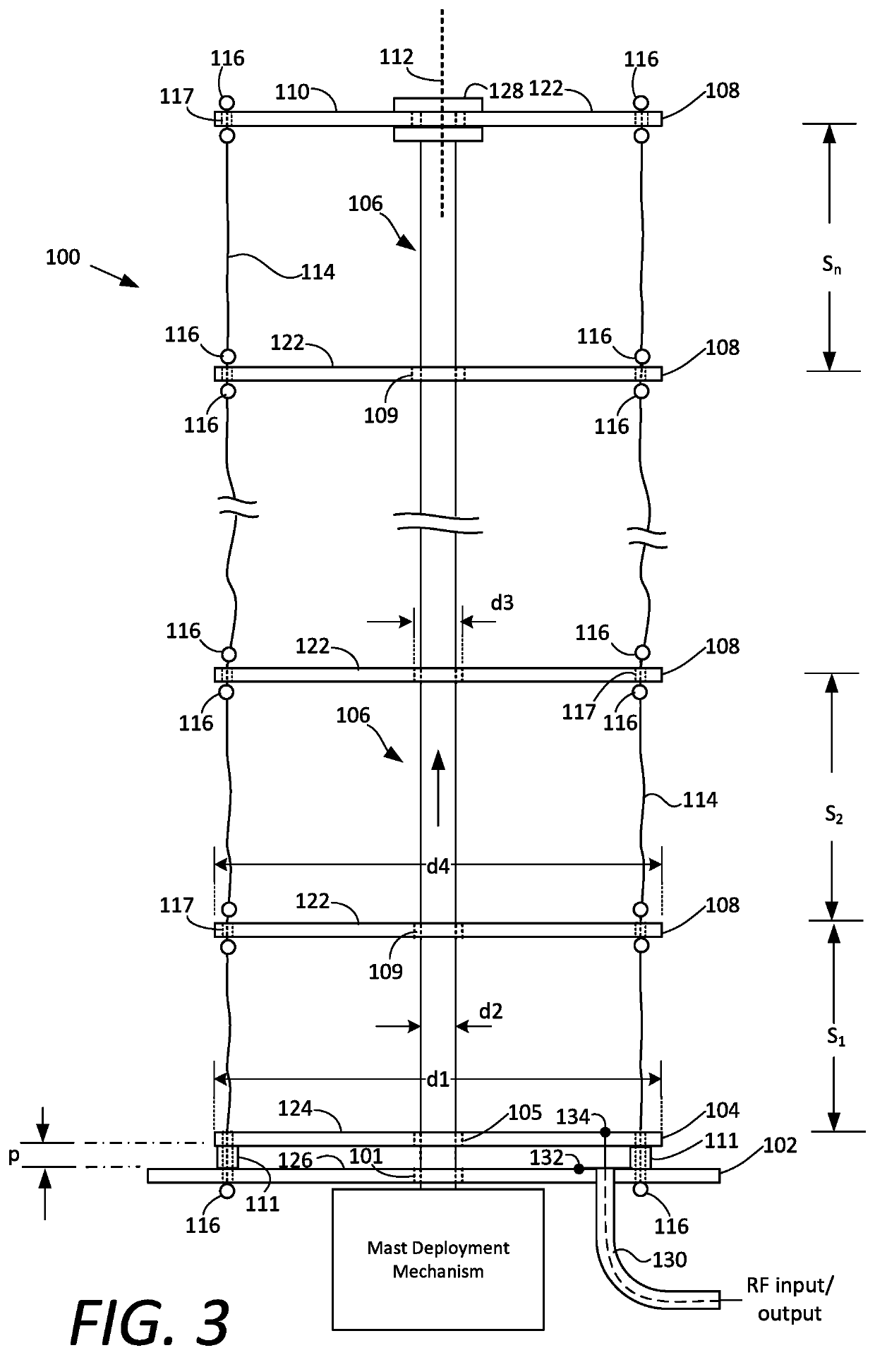
[0026]Certain aspects of a deployable antenna system described herein may be understood with reference to FIGS. 1-3. The disk antenna 100 is comprised of a plurality of plates which are arranged to form a stack 103. The plurality of plates include a ground plane plate 102, a plurality of electrically active plates 108, and a drive plate 104 that is disposed between the ground plane plate and the plurality of electrically active plates. The plates in the stack a...


PUM


Abstract

Disk antenna includes a plurality of conductive plates forming a stack aligned along a principal axis. The plates include a ground plane plate, a plurality of electrically active plates, and a drive plate disposed between the ground plane plate and the plurality of electrically active plates. A mast is configured to transition from a first condition in which the mast is compactly stowed, to a second condition in which the mast is deployed. Suspension members are configured to couple a radiating end of the mast to the plurality of electrically active plates. The plates are compactly stacked when the mast is in the first condition, and urged to distributed locations along the length of the mast in the second condition.

Description

BACKGROUNDStatement of the Technical Field[0001]The technical field of this disclosure concerns antenna systems, and more particularly methods and systems for implementing extremely compact high gain antennas which are deployable.DESCRIPTION OF THE RELATED ART[0002]Antennas are needed for a wide variety of applications, including space-based applications. When used in space-based applications, it is often necessary for an antenna system to be stowed compactly to facilitate transport into space. The same antenna must then be able to deploy automatically to its full size when it arrives at an on-orbit location. Relatively high gain is a necessary capability of certain types of communications systems, including satellite-based communication systems. Such high gain can be challenging to facilitate when the size of the antenna is constrained. For example, there is a growing need for high gain antenna systems which can be employed in CubeSats. CubeSats are a class of nanosatellites which ...

Claims


Application Information

Patent Timeline
Patent Type & Authority Patents(United States)
IPC IPC(8): H01Q1/00H01Q1/10H01Q1/36H01Q1/48H01Q1/12H01Q1/50H01Q1/28H01Q1/27
CPCH01Q1/36H01Q1/12H01Q1/1235H01Q1/1242H01Q1/27H01Q1/288H01Q1/48H01Q1/50H01Q19/185H01Q19/04H01Q1/10H01Q9/0414
Inventor PARSCHE, FRANCIS
Owner EAGLE TECH LLC
Why Eureka
Try Eureka