PTC device

a positive coefficient temperature and device technology, applied in resistors, resistor details, electrical devices, etc., can solve the problems of reducing the thickness of the protection device, too thin to be achieved, devices may topple, etc., to avoid rollover problems, simple pressing, and equal width and height

Active Publication Date: 2021-01-12
POLYTRONICS TECH
View PDF14 Cites 1 Cited by
  • Summary
  • Abstract
  • Description
  • Claims
  • Application Information

AI Technical Summary

Benefits of technology

[0006]The present application provides a PTC device characterized in over-current protection and / or over-temperature sensing. In view of simple structure and manufacturing process, the PTC device is suitable to be made in the sizes of 0402 or 0201. The PTC device has no internal circuit, and thus there is no concerns of material inflation and retraction and misalignment between internal and external circuits. Moreover, the PTC device still has prepreg supports at two sides, thereby enhancing structural strength and increasing manufacturing yield.
[0018]In accordance with the present application, the PTC device has no complicated internal circuit and therefore there is no concerns of inflation and retraction and misalignment between internal and external circuits. The PTC device can be simply made by pressing and is suitable to be made in small sizes such as 0402 or 0201. The PTC device may have equal width and height to avoid rollover issues.

Problems solved by technology

When the device is downsizing to form factor 0201, it is a great challenge on how to decrease the thickness of the protection device for surface-mount applications.
In manufacturing, the length and width are doable, but the thickness is too thin to be achieved.
As a result, the devices may topple when they are subjected to packaging or other processes afterwards.
Moreover, the internal-and-external circuit design on a small size device sometimes has misalignment between the internal circuit and external circuit, and therefore the production yield will be negatively impacted.
However, the electrode layers of the PTC device are not symmetrical, and therefore there is a need to verify the orientation of the PTC device under electric testing and packaging.
Moreover, the groove may be misaligned due to inflation and retraction of the PTC material during manufacturing, right and left electrodes of unequal areas influence electric characteristic.
Without support of prepreg layers, the PTC device may flaw due to insufficient strength during manufacturing.

Method used


Image

  • PTC device
  • PTC device
  • PTC device

Examples


Embodiment Construction

[0027]The making and using of the presently preferred illustrative embodiments are discussed in detail below. It should be appreciated, however, that the present application provides many applicable inventive concepts that can be embodied in a wide variety of specific contexts. The specific illustrative embodiments discussed are merely illustrative of specific ways to make and use the invention, and do not limit the scope of the invention.

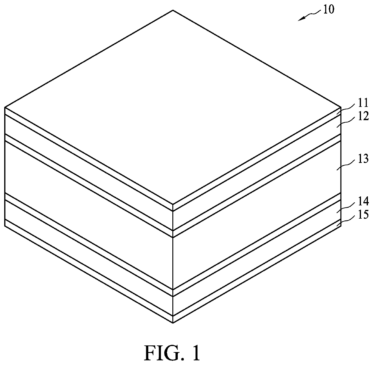
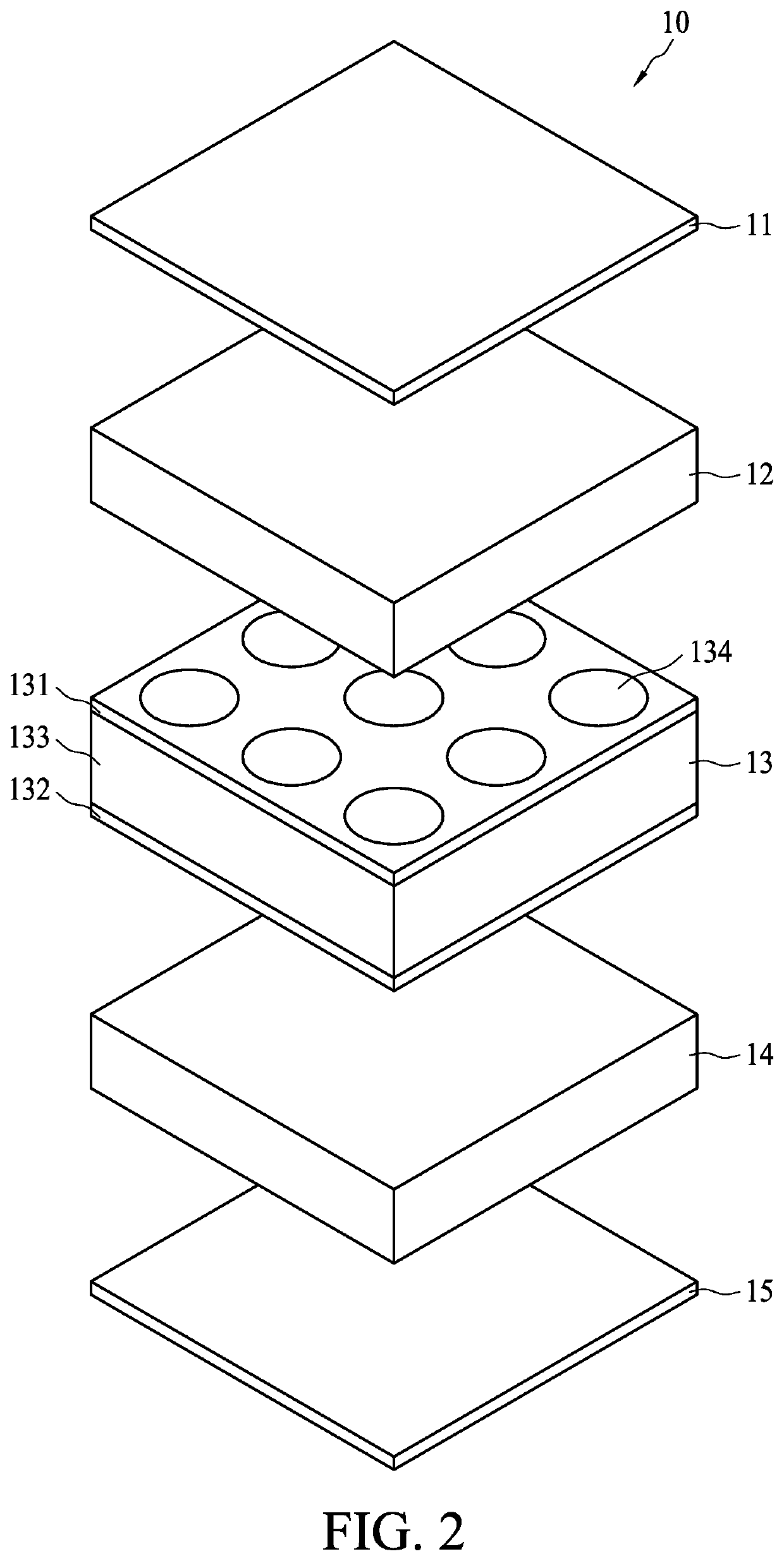
[0028]FIG. 1 shows a perspective view of a PTC device in accordance with an embodiment of the present application. FIG. 2 shows an exploded view of the PTC device in FIG. 1. A PTC device 10 comprises a first metal layer 11, a first PTC material layer 12, a laminated substrate 13, a second PTC material layer 14 and a second metal layer 15. The laminated substrate 13 comprises a first conductive layer 131, a second conductive layer 132 and an insulating layer 133 laminated between the first conductive layer 131 and the second conductive layer 132. Th...


PUM

PropertyMeasurementUnit
glass transition temperatureaaaaaaaaaa
thicknessaaaaaaaaaa
thicknessaaaaaaaaaa

Abstract

A PTC device comprises a laminated substrate, a first PTC material layer, a second PTC material layer, a first metal layer and a second metal layer. The laminated substrate comprises a first conductive layer, a second conductive layer and an insulating layer laminated between the first and second conductive layers. The first PTC material layer is disposed on the first conductive layer, and the second PTC material layer is disposed on the second conductive layer. The first metal layer is disposed on the first PTC material layer, and the second metal layer is disposed on the second PTC material layer. The insulating layer has a through hole filled with PTC material to form a PTC connecting member of which one end connects to the first PTC material layer and another end connects to the second PTC material layer.

Description

BACKGROUND OF THE INVENTION(1) Field of the Invention[0001]The present application relates to a thermistor. More specifically, it relates to a positive coefficient temperature (PTC) device.(2) Description of the Related Art[0002]PTC devices can be used for protecting circuitries from damages resulted from over-heat or over-current. A PTC device usually contains two electrodes and a resistive material disposed therebetween. The resistive material has PTC characteristic that the resistance thereof remains extremely low at room temperature and instantaneously increases to thousand times when the temperature reaches a critical temperature or the circuit has over-current so as to suppress over-current and protect the cell or the circuit device. Moreover, the PTC device can be applied to an over-temperature sensing circuit, it detects ambient temperature upon which proper action. e.g., power off, is activated for over-temperature protections. When the material gets back to the room temper...

Claims


Application Information

Patent Timeline
Patent Type & Authority Patents(United States)
IPC IPC(8): H01C7/02H01C1/14
CPCH01C7/027H01C1/1406H01C7/021H01C7/028
Inventor TSENG, CHUN-TENGCHANG, YAO-TELEE, WEN FENG
Owner POLYTRONICS TECH
Why Eureka
Try Eureka