
Water-cooled heat dissipating device

a heat dissipating device and water-cooled technology, applied in the direction of lighting, heating apparatus, semiconductor/solid-state device details, etc., can solve the problems of inability to perform the function of the impeller, damage or life shortening of the heating element, and the existing impeller is easy to stop rotating, so as to reduce the volume of the chamber and ensure the sufficiency of the coolant. , the effect of reliably monitoring

Active Publication Date: 2020-12-15
KUAN DING TECH
View PDF3 Cites 2 Cited by
  • Summary
  • Abstract
  • Description
  • Claims
  • Application Information

AI Technical Summary

Benefits of technology

[0004]An object of the invention is to provide a water-cooled heat dissipating device, which reduces volume of the chamber to conduce to driving the passive impeller to rotate so that sufficiency of the coolant can be reliably monitored.
[0008]In addition, both the first slant plates of the catchment tank and the blocking plates of the passive impeller makes the passive impeller be easily driven to rotate by a small flow force.

Problems solved by technology

When the coolant evaporates or is consumed or leaked, the coolant will be insufficient to cause damage or life shortening of the heating element.
However, existing impellers are easy to stop rotating because of a water flow direction or excessively large volume of the chamber in the water block.
This makes the impeller be not able to perform its function.

Method used


Image

  • Water-cooled heat dissipating device
  • Water-cooled heat dissipating device
  • Water-cooled heat dissipating device

Examples


Embodiment Construction

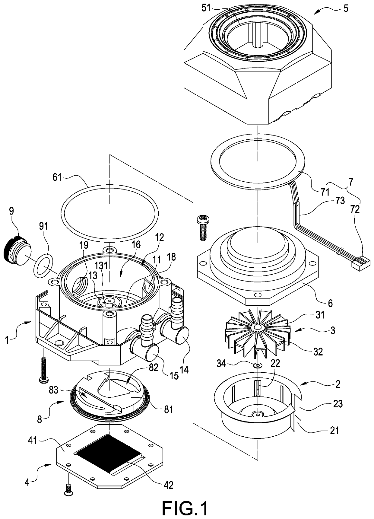
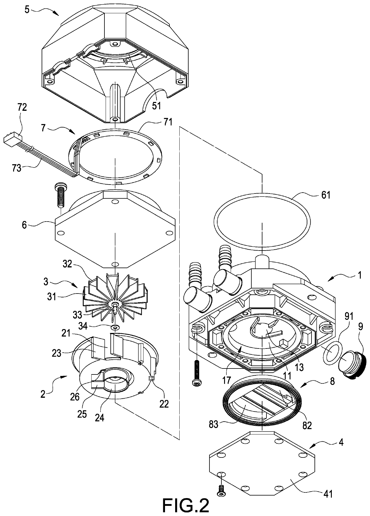
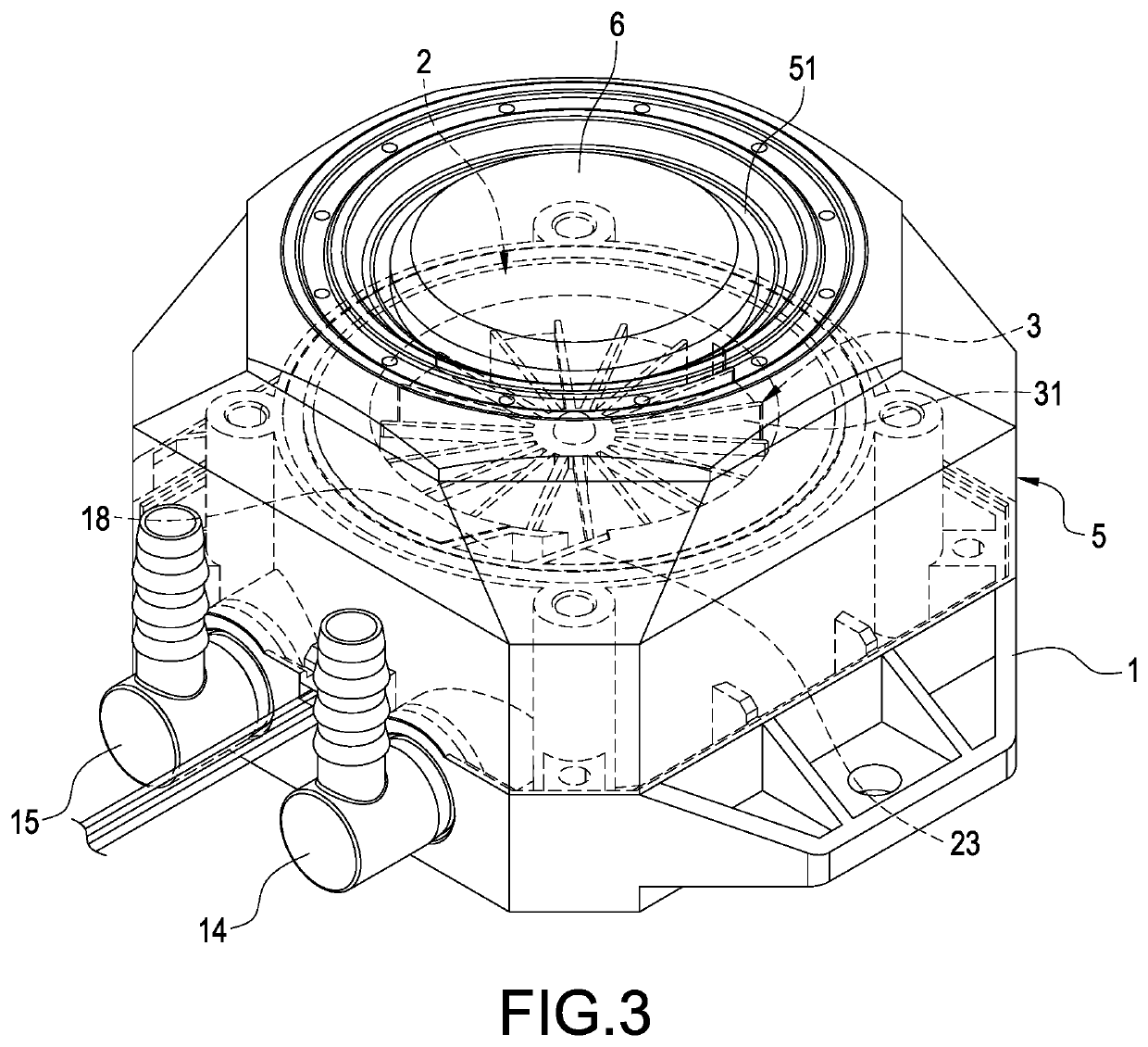
[0016]As shown in FIGS. 1-6, the invention provides a water-cooled heat dissipating device for conveying a working fluid (not shown). The, working fluid (i.e. coolant) possesses functions of antifreeze, anti-rust and anti-corrosion and can be added with colored pigment to perform personal style or visual effect. The water-cooled heat dissipating device mainly includes a base 1, a passive impeller 3 and a cold plate 4. The water-cooled heat dissipating device mainly of the embodiment further includes a catchment tank 2, a top cover 5 assembled on the base 1, a transparent cover plate 6 disposed between the base 1 and the top cover 5, a lighting module 7 disposed between the top cover 5 and the transparent cover plate 6 and a water-resistant O-ring 61 disposed between the base 1 and the transparent cover plate 6. The top cover 6 is formed with a concave opening 51 for exposing part of the transparent cover plate 6.

[0017]The base 1 includes a division plate 11, a chamber 12, a flow gui...


PUM


Abstract

A liquid cooling device includes a base (1), a passive impeller (3) and a cold plate (4). The base (1) includes a division plate (11), a chamber (12) and a flow guiding pole (13). The division plate (11) divides the chamber (12) into a catchment portion and a heat exchanging portion (17). The flow guiding pole (13) communicates with both the catchment portion (16) and the heat exchanging portion (17). The passive impeller (3) is received in the chamber (12) and radially driven to rotate by the working fluid. The cold plate (4) is arranged correspondingly to the heat exchanging portion (17) and fastened to the base (1).

Description

BACKGROUND OF THE INVENTIONTechnical Field[0001]The invention relates to heat dissipating devices, particularly to liquid-cooled heat dissipating devices.Related Art[0002]A currently available water (liquid) cooling system includes a water tank, a water block attached on a heating element, a water pump connected to the water tank, a water-to-air heat exchanger, coolant and pipes for rapidly dissipating heat form the heating element. In comparison with air cooling, water cooling has advantages of higher heat dissipation efficiency, lower noise and colorful visual effect, so it has been widely applied in personal computers. When the coolant evaporates or is consumed or leaked, the coolant will be insufficient to cause damage or life shortening of the heating element.[0003]To solve the above problem, some manufacturers install an impeller in the water block to indicate whether the coolant is sufficient or not. Stopping rotating of the impeller means coolant is needed to be supplemented...

Claims


Application Information

Patent Timeline
Patent Type & Authority Patents(United States)
IPC IPC(8): F28D15/02F28F13/06F28D15/00H01L23/473F28F13/12
CPCF28D15/0233F28F13/06F28D15/00F28F13/12H01L23/473G06F1/20G06F2200/201
Inventor PAN, KUAN-DACHANG, NENG-CHAOPENG, MING-CHENGCHAO, PEI-CHING
Owner KUAN DING TECH
Learn More