
Leg exercise device

a leg exercise and leg technology, applied in the field of leg exercisers, can solve the problems of increasing the risk of pulmonary embolism or deep vein thrombosis (dvt) occurring in the lower legs, and achieve the effect of reducing the volume of the first chamber, reducing the volume of the second chamber, and reducing the volume of the set of chambers

Inactive Publication Date: 2006-07-13
SARMA VIMALA
View PDF10 Cites 2 Cited by
  • Summary
  • Abstract
  • Description
  • Claims
  • Application Information

AI Technical Summary

Benefits of technology

[0006] Where part of a chamber wall is flexible, the volume of one chamber may be reduced by pressing directly on the flexible wall. The volume may also be reduced indirectly by pressing on a pressure plate or the like that in turn, directly or indirectly, presses on the flexible wall or otherwise reduces the volume of the chamber.
[0021] In one preferred embodiment, pushing downwards with the ball of the user's foot reduces the volume of the first chambers whilst pushing downwards with the heel of the user's foot reduces the volume of the second chambers. As the volume of a set of chambers is reduced the volume of the other set of chambers is increased.

Problems solved by technology

This results in an increased risk of deep vein thrombosis (DVT) occurring in the lower legs or pulmonary embolisms.

Method used


Image

  • Leg exercise device
  • Leg exercise device
  • Leg exercise device

Examples


second embodiment

[0051] FIGS. 7 to 11 show the invention intended for use in public transport vehicle, such as airplanes, trains and long haul coaches. The device 50 is intended as a replacement for the footrests commonly found in these vehicles. The device 50 comprises an upper base unit 52 and a lower base unit 54 connected to each other about a hinge 56. The two base units 52, 54 are rotatable between an open position (FIGS. 7 and 8) in which they lie generally in a plane and a closed position in which the lower base unit lies on top of the upper base unit (FIG. 9) at approximately 180° to the open position. The upper base unit 52 is provided with mountings 57 by which it may be mounted to a seat in front of the seat of the user. The mounting 57 preferably allows the upper base unit 52, together with the lower base unit 54, to be pivoted out of the way when desired.

[0052] The two base units are sized so that a user may place their two feet side by side on the device with the heels of the feet res...

first embodiment

[0053] Located on the upper surface of the upper base unit 52 are two upper chambers 58 and 60. As with the first embodiment these chambers are partially defined by a flexible membrane 62 that, in use, extends above the general plane of the upper surface 64 of the upper base unit 52.

[0054] The lower base unit 54 is similar to the upper base unit 52 and is provided with lower chambers 66 and 68. These chambers are also partially defined by flexible membranes 70 that, in use, extend above the general plane of the upper surface 72 of the lower base unit 54.

[0055] The upper and lower chambers 58, 60, 66, 68 communicate with each other via tubes 74 that connect to the rear of the base units 52, 54 and communicate with the chambers via passageways 76 extending through the respective base unit to open within the chambers.

[0056] The tubes extend to a valve unit 80 positioned on the upper base unit 52. The valve unit 80 controls how the chambers communicate with each other.

[0057] Referrin...


PUM


Abstract

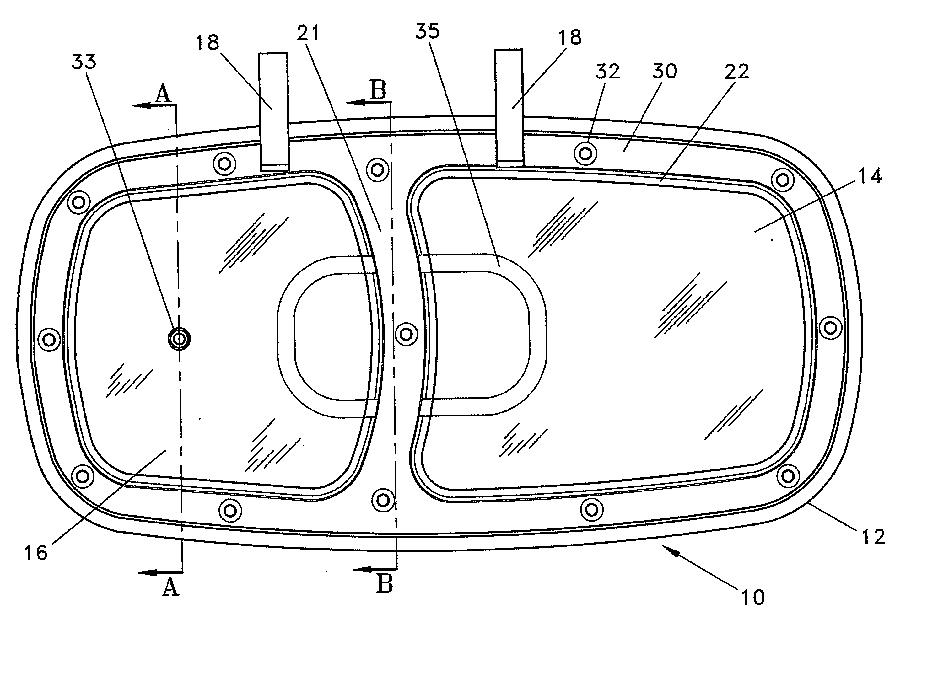
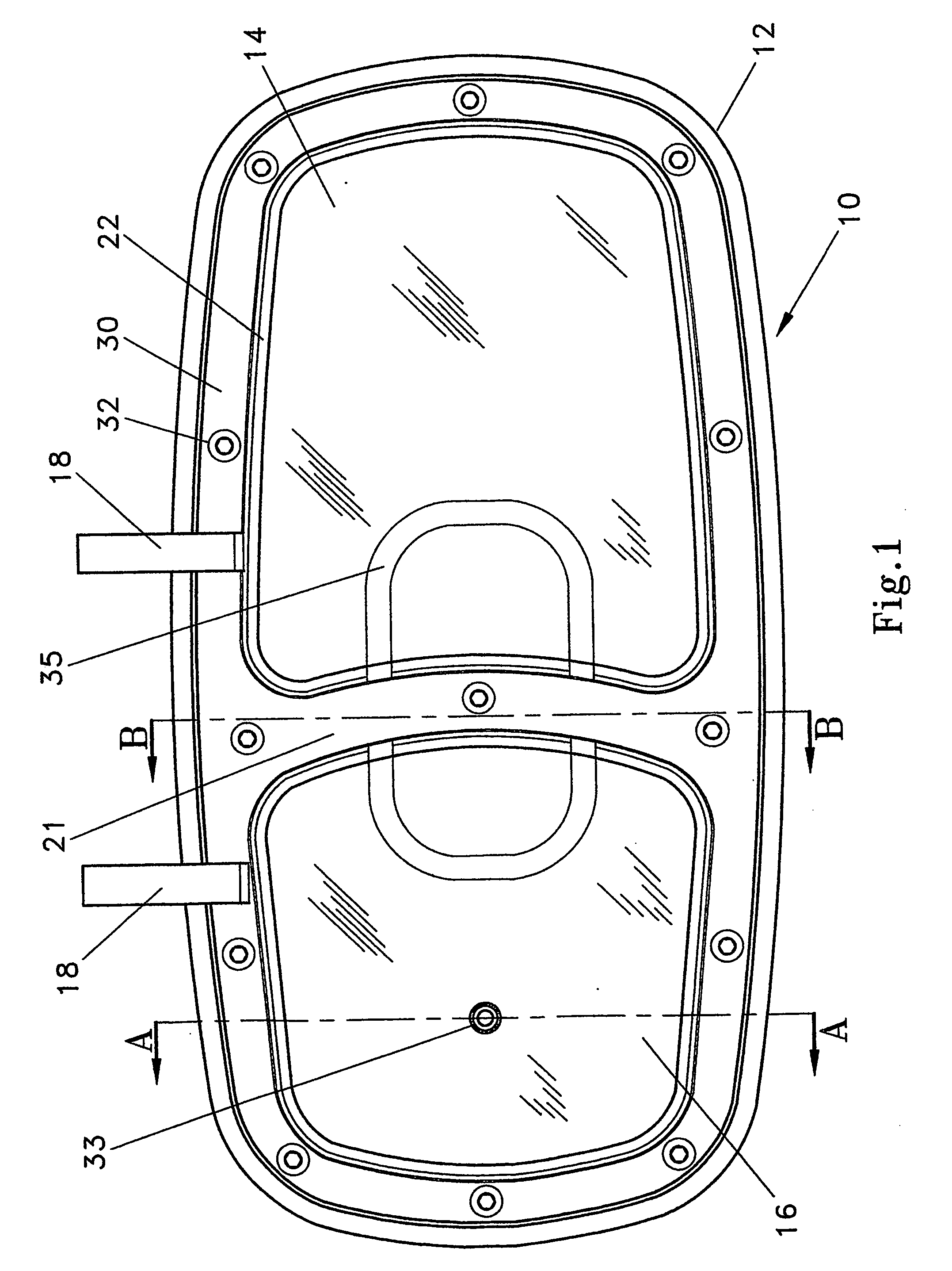
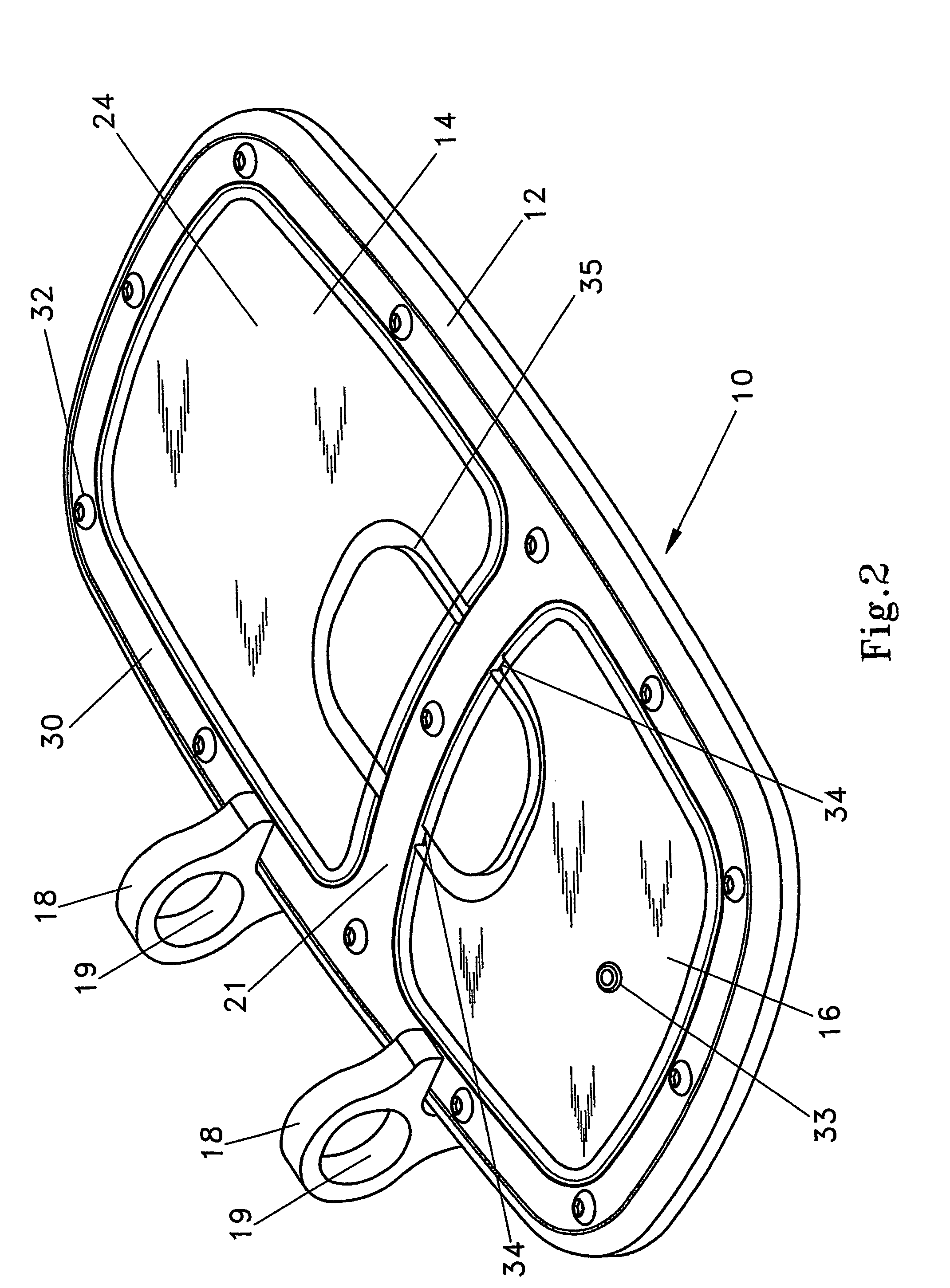
A foot and / or leg-exercising device (10) has a first sealed chamber (14) and a second sealed chamber (16) that are interconnected via one or more passageways (34). The chambers (14, 16) are of variable volume and fluid within one chamber may be pumped to the other chamber using the feet and / or legs. In one embodiment each foot is provided with a first chamber and a second chamber and fluid is pumped by a heel and toe rocking action of each foot. The chambers for both feet may be interconnected to allow pumping by an up and down action of the legs.

Description

TECHNICAL FIELD [0001] This invention relates to a leg exerciser and more particularly to a device that allows exercise of the lower legs when sitting or lying. BACKGROUND ART [0002] When sitting or lying relatively still for long periods of time pooling of fluids occurs in the lower legs. This results in an increased risk of deep vein thrombosis (DVT) occurring in the lower legs or pulmonary embolisms. Although DVT has become well known due to a higher incidence occurring with long haul air travel, sitting still for long periods, such as in trains, buses or wheelchairs or lying, such as in a hospital bed, is also believed to result in DVT in some people. Leg and / or foot exercise whilst sitting or lying is believed to reduce the risk of DVT occurring. Exercising the feet and legs is also recommended for rehabilitation after hospitalisation or immobilisation for any reason, including after operative procedures, injure, stoke, etc. for example, when a person has been injured and has b...

Claims


Application Information

Patent Timeline
IPC IPC(8): A63B21/008A63B22/16A63B23/035
CPCA63B21/0081A63B21/0085A63B22/16A63B23/03533A63B2225/30A63B21/00069A61H2209/00A63B21/008
Inventor SARMA, VIMALA
Owner SARMA VIMALA
Learn More