
Drywall construction combination profiled section for walls and ceilings of a house

a profiled section and drywall technology, applied in the direction of walls, constructions, building components, etc., can solve the problems of unsuitable for absorbing static loads of drywall, difficult processing of thick-walled drywall construction profiled sections, and difficulty in cladding with building panels, so as to reduce body shell costs, reduce the cost of body shell, and use less material

Active Publication Date: 2020-12-15
SCHURIG BURKHART
View PDF46 Cites 0 Cited by
  • Summary
  • Abstract
  • Description
  • Claims
  • Application Information

AI Technical Summary

Benefits of technology

The invention is a drywall construction system that combines the benefits of steel and drywall construction. The system uses a combination profiled section made of thin-walled steel and standard drywall construction sections. This profiled section allows for easy and cost-effective cladding to be added onto a construction site using simple technology. This system simplifies the processing of static drywall construction and reduces the body shell costs. The drywall construction combination profiled section can be used for both walls and ceilings, providing flexibility in construction options. The invention also provides a solution for ambitious drywall construction companies looking to expand their business by offering static house building as a line of business. Overall, the invention improves the stability and efficiency of drywall construction, making it a more viable option for both builders and homeowners.

Problems solved by technology

However, the processing of the thick-walled drywall construction profiled sections is more difficult because of the connecting means, the static details, building approval and design safety, and therefore very few trade enterprises deal with this issue.
A starting sheet which is necessarily thicker-walled for static house building then also has a large sheet metal thickness at the cladding sections, which makes cladding with building panels more difficult, and also in the case of any other thick-walled profiled section.
Problem: standard drywall construction profiled sections with a sheet metal thickness of approx.
0.6 mm permit simple manual cladding with building panels on stud walls and joists, but said lightweight drywall construction profiled sections are unsuitable for absorbing static loads of a house.
Although the stability in drywall construction is significantly increased with the use of thicker-walled lightweight steel profiled sections, this necessitates more costly cladding installation technologies which increase the construction costs, require specialists as fabricators, do not permit any personal contributions and therefore reduce acceptance among builders.
Structures which are capable of being load-bearing and have very thin-walled steel profiled sections generally require a plurality of components of intermediate members or complicated expensive profiled section configurations which can make the installation outlay too costly.
On account of safety and safeguarding aspects, statically relevant activities always require a specialized installation team which, however, may be limited only to the core task of “static body shell”, i.e. primarily realizes the connection of the thick-walled static profiled sections to one another.
The static determination of thicker-walled steel profiled sections permits a recognized dimensioning of structures and, in contrast thereto, saves costly individual testing of very thin-walled steel sheet metal profiled sections of the drywall construction that are used repeatedly or in interlaced form.
Although semifinished product sheet metal bands of different thickness within the band are theoretically known in the form of tailor welded coils or tailor rolled coils for roll forming, they are not available in practice.

Method used


Image

  • Drywall construction combination profiled section for walls and ceilings of a house
  • Drywall construction combination profiled section for walls and ceilings of a house

Examples


Embodiment Construction

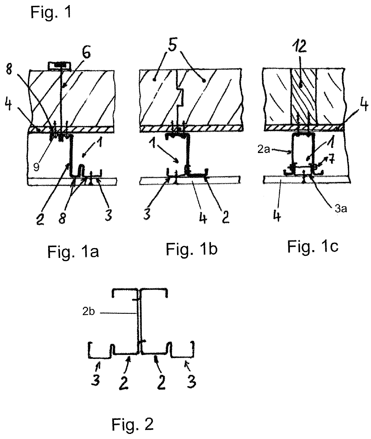
[0031]FIG. 1: the exemplary embodiment shows horizontal cross sections through a drywall construction wall with three different drywall construction combination profiled sections (1) which are set vertically and anchored as wall studs in horizontal U foot and U head profiled sections. The outer building panel (4) serves primarily for structural wall reinforcement and consists of an OSB panel coated with insulating materials and is part of a wall body (5) which is screwed from the inside to the static section (2) of the drywall construction combination profiled sections (1).

[0032]The wall bodies (5) with the dimensions of approx. 60 cm×250 cm and peripheral tongue and groove system are plugged together in a horizontal offset with the profiled sections overlapping and are screwed to the static sections (2) of the wall inner side. In the area of the story ceiling, a wall body (5) overlaps both the studs of the ground floor and of the first floor. The outer insulating layer also serves ...


PUM


Abstract

A wall construction system having drywall construction combination profiled sections, and a method for constructing a wall. Standard drywall construction profiled sections using sheet metal that is approximately 0.6 mm thick allow easy manual sheathing of stud walls with building panels, but lightweight sheet metal profiled sections of this type are not suitable for bearing static loads of a house. Thicker walled lightweight steel profiled sections greatly improve stability but require more costly assembly technologies needing specialists, which increases construction costs and therefore stops drywall-constructed housing from becoming more widespread. The new combination profiled sections provide for statically stable construction systems that can nevertheless be worked and sheathed simply and easily. The present drywall construction combination profiled section includes two functional sections. A statically stable section which has splayed flanges, and a section having a planar thin-walled drywall construction contact surface, acting as a sheathing section.

Description

CROSS-REFERENCE TO RELATED APPLICATIONS[0001]This application is the U.S. national phase of PCT Application No. PCT / DE2017 / 000345 filed on Oct. 17, 2017, which claims priority to DE Patent Application No. 10 2016 12 397.4 filed on Oct. 17, 2016, the disclosures of which are incorporated in their entirety by reference herein.TECHNICAL FIELD[0002]The invention relates to a drywall construction combination profiled section for erecting statically load-bearing walls and ceilings for drywall construction houses. The substantial static loadings of the house are absorbed by the aligned perpendicular wall studs which are arranged in a grid and consist of combination profiled sections which are each enclosed at their end points in U lightweight steel profiled sections and are clad on both sides with building panels. Infilling wall bodies can be arranged between the profiled sections.[0003]At drywall construction stud walls, the composite effect of compression-loaded studs and the extensively...

Claims


Application Information

Patent Timeline
IPC IPC(8): E04B2/78E04B2/74
CPCE04B2/7881E04B2/7457E04B2/789E04B2/7854
Inventor SCHURIG, BURKHART
Owner SCHURIG BURKHART
Learn More