Vivaldi notch waveguide antenna

a waveguide antenna and notch technology, applied in the direction of antennas, electrical equipment, antennas, etc., can solve the problems of physical implementation degraded performance and further challenge of conventional antenna performance, and achieve the effect of suppressing the higher frequency general end fire characteristics of the antenna, enhancing the end fire slot vswr component of the antenna bandwidth, and improving gain characteristics

Active Publication Date: 2020-12-08
CRUISE IAN GERARD MR
View PDF23 Cites 1 Cited by
  • Summary
  • Abstract
  • Description
  • Claims
  • Application Information

AI Technical Summary

Benefits of technology

[0013]The method of the present invention provides enhancements to prior art Vivaldi antenna designs through multiple features which work together to provide improved performance in a compact size. In particular, rather than follow the classic straight line, a slot of the invented antenna has been curved at its origin in order to reduce the length, and a petal shaped section has been added to the signal side in order to narrow and shape the bandwidth.
[0016]In certain alternate preferred embodiments, the petal is shaped like a triangle and is located on the signal side within the area defined by the notch on the waveguide side. This feature serves to enhance the end fire slot VSWR component of the antenna bandwidth, providing better gain characteristics in this band, while at the same time suppressing the higher frequency general end fire characteristics of the antenna.
[0017]In certain preferred embodiments, a microstrip extends from the triangular petal and substantively follows a portion of the slot line on the waveguide side. This feature serves to enhance the bandwidth narrowing and shaping aspects of the petal feature. In a conventional Vivaldi antenna, the slot line extends in a straight line from the Vivaldi horn feature of the antenna and may end in a slot stub feature of some sort. The signal microstrip of this conventional antenna is usually positioned at a right angle to the slot line and crosses it at a right angle. The microstrip extending from the petal of some embodiments of the present invention would interfere with the signal microstrip if added to this conventional design. Instead, the signal microstrip is moved off center of the Vivaldi horn feature and rotated to be parallel to the mouth of the Vivaldi horn feature. The slot line curves through a right angle and crosses the signal microstrip at its off center position.
[0018]The right angle turn of the slot line to accomplish the off center and parallel positioning of the signal microstrip can be accomplished by a sharp turn combined with an anti-reflection feature near the turn, but it can also be accomplished by a gradual circular turn. The latter method allows the petal microstrip to better align with the slot line through the turn, and is therefore a preferred embodiment.
[0019]In certain preferred embodiments where an antenna is comprised of multiple Vivaldi horns, additional inventive features on the waveguide side of the antenna improve the group characteristics of the Vivaldi horns. The end of the waveguide plate of the PCB opposite the end of the Vivaldi horns tends to be grounded. The size and shape of the ground plane formed between the slot line and the grounded end greatly affects the characteristics of the antenna, especially the planar characteristics. So that the characteristics of this ground plane can remain identical for each of the Vivaldi horns, the ground plane specific to each given Vivaldi horn shape can be separated from a ground strip along the end of the PCB by a narrow ground connection. In this fashion, any number of Vivaldi horns with repeatable characteristics can be combined on a single PCB.
[0020]In certain preferred embodiments where an antenna is comprised of multiple Vivaldi horns, additional inventive features on the signal side of the antenna improve the group characteristics of the Vivaldi horns. A balanced network of signal microstrips extending from a single original signal microstrip may be constructed such that the impedance of the original signal microstrip matches the impedance of each of the signal microstrips associated with each Vivaldi horn feature. This improves the transmission and reception characteristics of the Vivaldi horns operating in unison. Generally, a number of Vivaldi horns equal to a power of two is best suited for the application of this impedance balanced signal network. Thus, antennas comprising two or four Vivaldi horns are popular instances of this preferred embodiment.

Problems solved by technology

The performance of physical implementations of conventional antennas is degraded by a number of complicating factors, and when the size is compromised, the performance is further challenged.

Method used


Image

  • Vivaldi notch waveguide antenna
  • Vivaldi notch waveguide antenna
  • Vivaldi notch waveguide antenna

Examples


Embodiment Construction

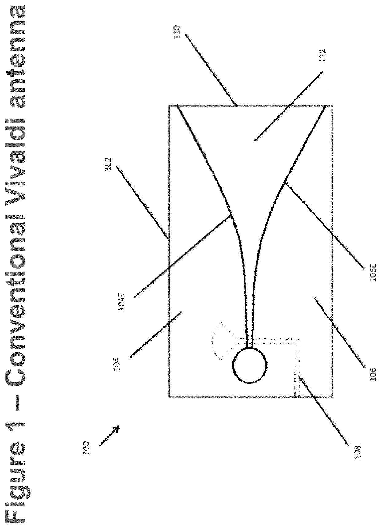
[0037]FIG. 1 is a diagram showing a conventional Vivaldi antenna implementation 100 including a conducting waveguide layer 102 comprising two symmetrical conducting wings 104&106 and a signal microstrip 108 (shown in dotted lines) which is typically placed on the opposite side of a coupled printed circuit board 110. The printed circuit board 110 may comprise a sheet of RF4 high-pressure thermoset plastic laminate material.

[0038]Each of the conducting wings 104&106 has an inner edge 104E &106E which is cut away along an exponential curve. A flared notch 112 is thereby formed between the two conducting wings 104&106. Radio frequency waves are theorized to radiate from a corresponding point along an axis at which the width of the flared notch is equal to λ / 2.

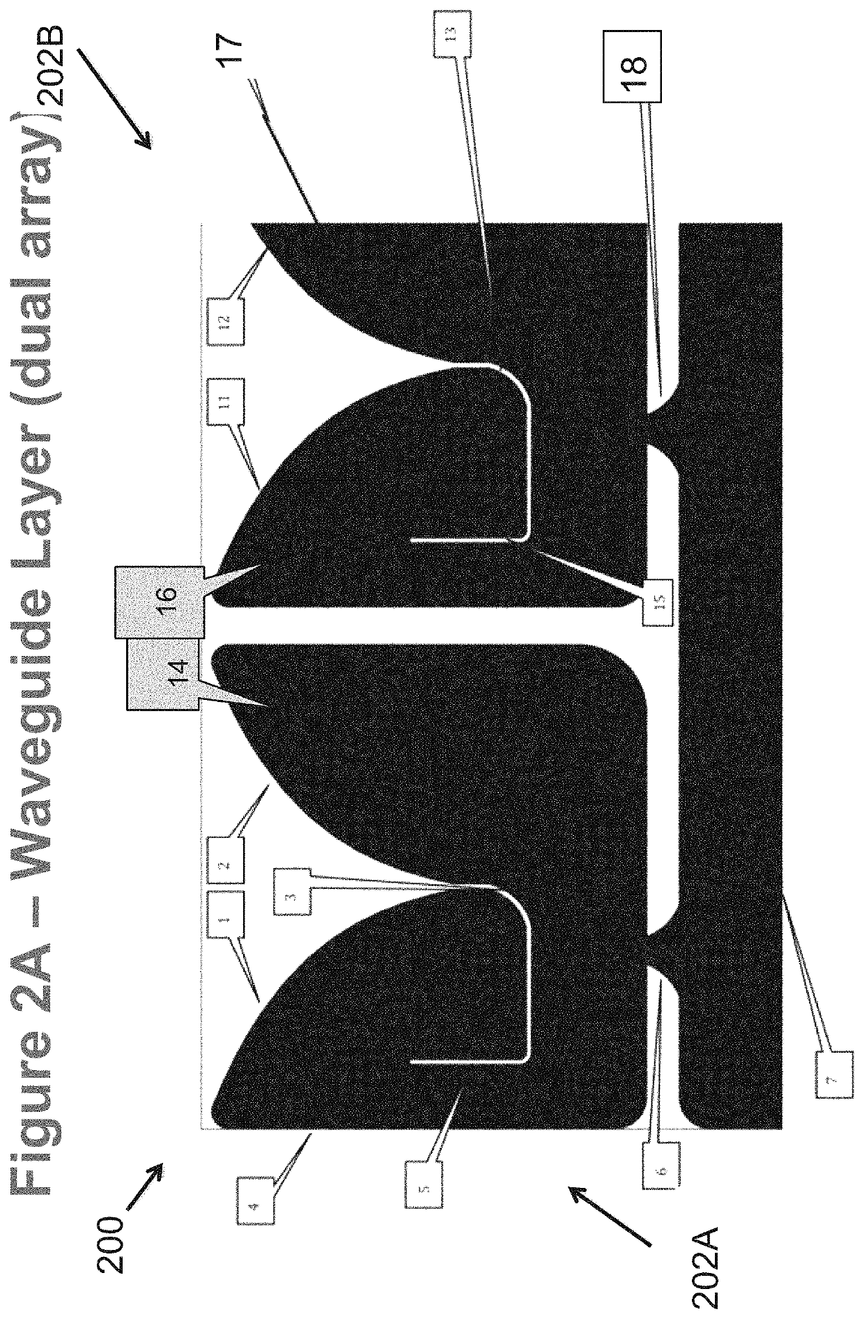
[0039]FIG. 2A is a diagram of the waveguide layer for one embodiment of the present invention 200 (hereinafter, “the dual element array”200) incorporating dual Vivaldi horns 202A &202B formed into an array. The familiar exponential...


PUM


Abstract

An improved Vivaldi antenna enhances the performance over a 2:1 frequency band while occupying a compact format. Taking advantage of a common FR4 material printed circuit board construction, considered features are added which improve the operating bandwidth without adding additional cost. One such embodiment operates over an approximate frequency range of 400 to 900 MHz.

Description

CO-PENDING PATENT APPLICATION[0001]This Nonprovisional Patent Application is a Continuation-in-Part Patent Application to U.S. Provisional Patent Application Ser. No. 62 / 687,345 Titled VIVALDI NOTCH WAVEGUIDE ANTENNA as filed on Jun. 20, 2019 by Inventor James Carlson. Provisional Patent Application Ser. No. 62 / 687,345 is hereby incorporated by reference in its entirety and for all purposes, to include claiming benefit of the priority date of filing of Provisional Patent Application Ser. No. 62 / 687,345.FIELD OF THE INVENTION[0002]The present invention relates to wireless communications technology. More particularly, the present invention relates to the structure and design methods of wireless communications antennas.BACKGROUND OF THE INVENTION[0003]The subject matter discussed in the background section should not be assumed to be prior art merely as a result of its mention in the background section. Similarly, a problem mentioned in the background section or associated with the subj...

Claims


Application Information

Patent Timeline
Patent Type & Authority Patents(United States)
IPC IPC(8): H01Q1/32H01Q21/06H01Q13/08
CPCH01Q13/085H01Q21/064H01Q21/08
Inventor CARLSON, JAMES
Owner CRUISE IAN GERARD MR
Why Eureka
Try Eureka