
Actuator for high-speed switch

a high-speed switch and actuator technology, applied in the direction of circuit-breaking switches, switch power arrangements, relays, etc., can solve the problems of large shock and electrode damage, and achieve the effect of reducing the speed of the driving unit and moving faster

Active Publication Date: 2020-12-08
HYOSUNG HEAVY IND CORP
View PDF35 Cites 0 Cited by
  • Summary
  • Abstract
  • Description
  • Claims
  • Application Information

AI Technical Summary

Benefits of technology

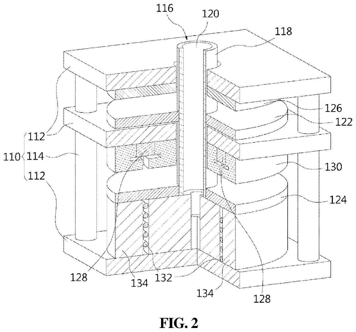
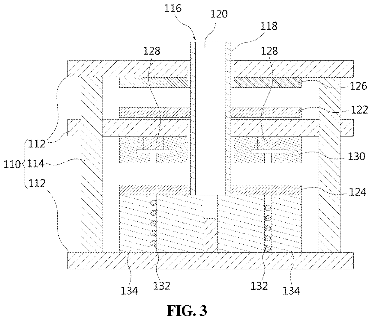
The present invention is a device with a unique opening and closing operation. When the device is opened, the force provided by the permanent magnet and elastic member is required to be overcome, allowing for quicker opening. When the device is closed, the force of the permanent magnet and elastic member is low, reducing the shock experienced when closing the device. Additionally, a shock absorbing portion is provided to further reduce the speed and absorb the shock during the opening operation. Overall, this invention provides a more efficient and safe device for opening and closing electrical contacts.

Problems solved by technology

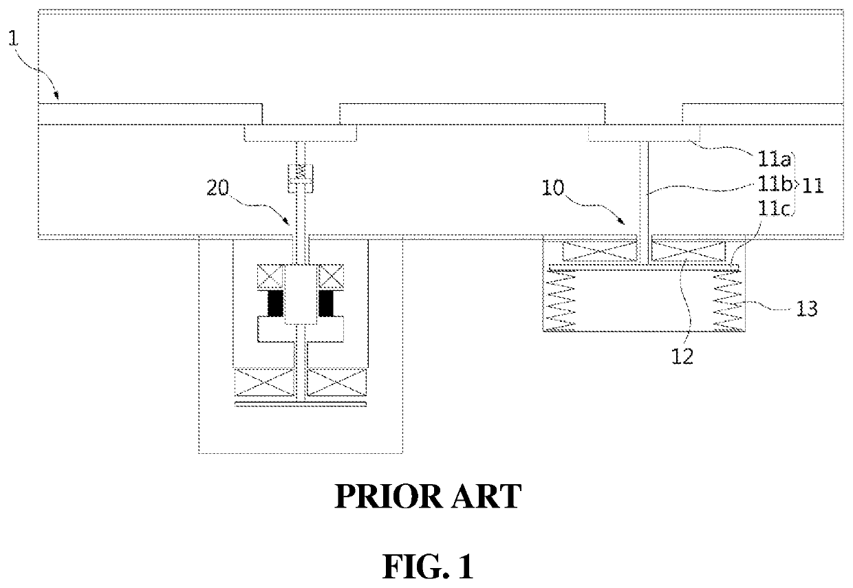
Here, if the restoring force of the spring 13 is large, the shock also becomes large, and damage to the electrode occurs.

Method used


Image

  • Actuator for high-speed switch
  • Actuator for high-speed switch
  • Actuator for high-speed switch

Examples


Embodiment Construction

[0025]Reference will now be made in greater detail to an exemplary embodiment of the present invention, an example of which is illustrated in the accompanying drawings. Wherever possible, the same reference numerals will be used throughout the drawings and the description to refer to the same or like parts. In the following description of the invention, if the related known functions or specific instructions on configuring the gist of the present invention unnecessarily obscure the gist of the invention, the detailed description thereof will be omitted.

[0026]Furthermore, it will be understood that, although the terms first, second, A, B, (a), (b), etc. may be used herein to describe various elements, these elements should not be limited by these terms. These terms are only used to distinguish one element, from another element. It will be understood that when an element is referred to as being “coupled” or “connected” to another element, it can be directly coupled or connected to the...


PUM


Abstract

An actuator for a high-speed switch is proposed. The actuator can include a frame having multiple mounting plates and columns. The mounting plates have parts installed thereon or movably supported thereby. The columns maintain the space between the mounting plates. A permanent magnet is installed on one of the mounting plates so as to face the second driving plate, and an elastic member is installed on the mounting plate that faces the mounting plate having the permanent magnet installed thereon, so as to provide force for the movement of the second driving plate.

Description

TECHNICAL FIELD[0001]The present invention relates generally to an actuator for a high-speed switch. More particularly, the present invention relates to an actuator for a high-speed switch, the actuator configured to perform an operation for DC blocking.BACKGROUND ART[0002]Recently, there have been many studies on high voltage direct current (HVDC), and of interest is a voltage conversion technology which has many advantages in constructing a terminal network compared to current conversion technology which has been widely used. In this regard, unlike other DC blocking methods, high-speed blocking characteristics with low loss are required, and many actuators for a high-speed switch used in DC are being studied.[0003]The document of Korean Patent No. 10-1444729 will be described in the following prior art document. The configuration of the prior art document is disclosed in FIG. 1 of this specification. Here, a high-speed switch 10 and a low-speed switch 20 for opening and closing a ...

Claims


Application Information

Patent Timeline
Patent Type & Authority Patents(United States)
IPC IPC(8): H01H77/00H01H50/22H01H50/04H01H33/38H01H33/28H01H50/30H01H50/44H01H50/36H01H50/64H01H71/24H01H73/36H01H71/32H01H3/60H01H33/666H01H3/28H01H33/59H01H50/32
CPCH01H50/30H01H50/04H01H50/22H01H33/285H01H33/38H01H50/44H01H2050/446H01H50/641H01H73/36H01H71/24H01H33/596H01H50/36H01H71/32H01H3/28H01H50/32H01H3/60H01H33/6662
Inventor AN, HYUN MOHWANG, HUI DONGSIM, DONG JOON
Owner HYOSUNG HEAVY IND CORP
Learn More