Magnetic powder dust core with entirely buried coil or magnet
a dust core and magnetic powder technology, applied in the direction of dynamo-electric machines, magnetic circuit rotating parts, magnetic circuit shape/form/construction, etc., can solve the problems of difficult deformation of dust core, and low mechanical strength of dust cor
- Summary
- Abstract
- Description
- Claims
- Application Information
AI Technical Summary
Benefits of technology
Problems solved by technology
Method used
Image
Examples
first embodiment
[0045]First, a first embodiment of an electrically powered machine according to the invention will be described. In addition, in this specification, an “electrically powered machine” refers to an electric motor (a motor), a power generator (a generator), or an electric motor-generator (a motor-generator) having the functions of both the electric motor and the power generator.
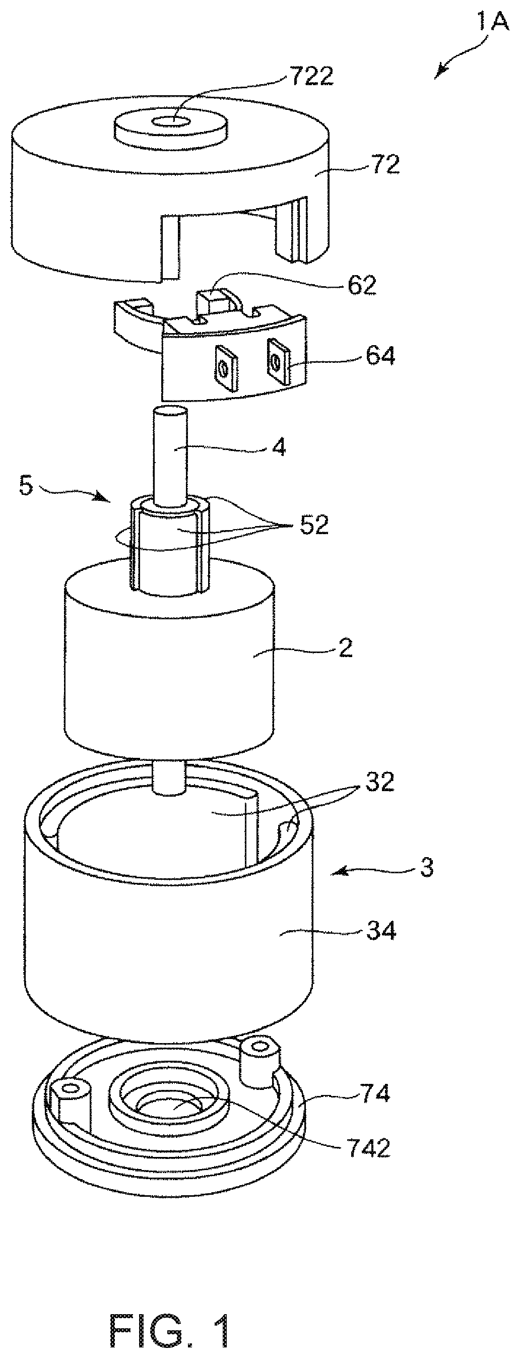
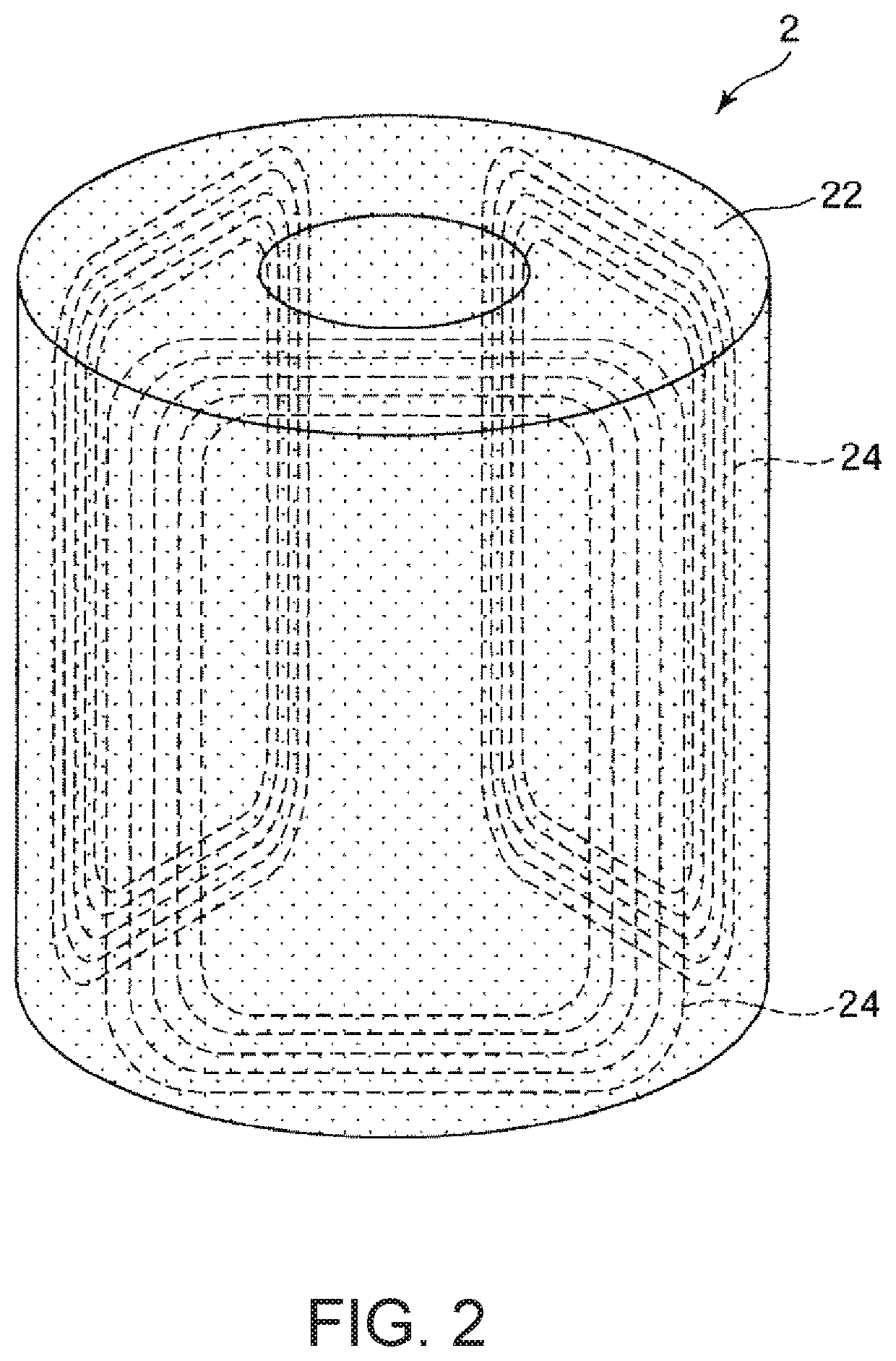
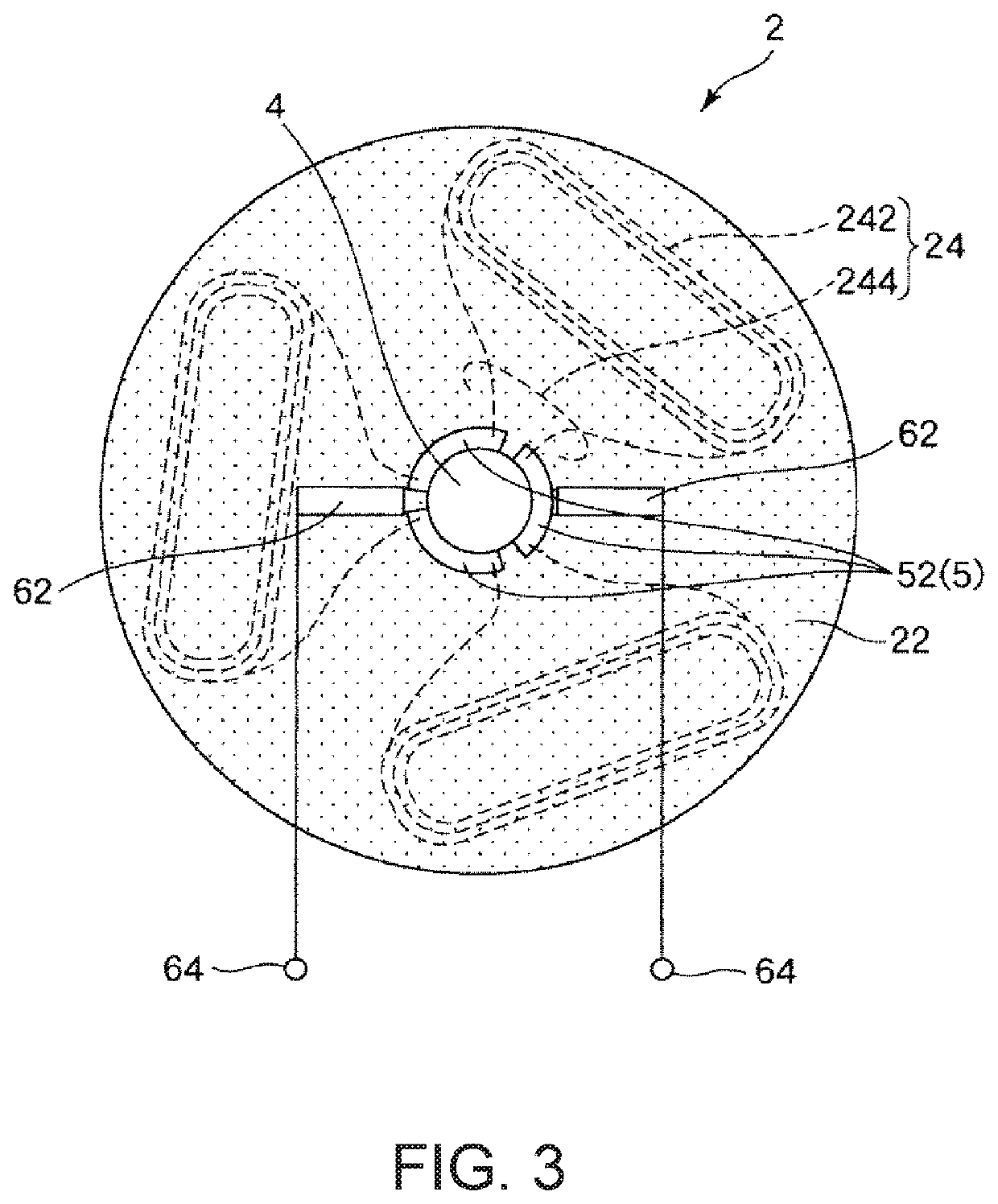
[0046]FIG. 1 is an exploded perspective view showing a direct-current electric motor (a DC motor) to which the first embodiment of the electrically powered machine according to the invention is applied. Further, FIG. 2 is a transparent perspective view showing an armature of the direct-current electric motor shown in FIG. 1, and FIG. 3 is a plan view when the armature shown in FIG. 2 is viewed from an extended line of a rotary shaft, and is a diagram showing such an armature, and a shaft, a commutator, and a brush which are associated with the armature. Further, FIG. 4 is a cross-sectional view when the direct-c...
second embodiment
[0078]Next, a second embodiment of the electrically powered machine according to the invention will be described.
[0079]FIG. 5 is an exploded perspective view showing an axial gap type brushless direct-current electric motor to which the second embodiment of the electrically powered machine according to the invention is applied.
[0080]Hereinafter, the second embodiment will be described. However, in the following description, description will be made focusing on differences from the first embodiment described above, and with respect to the same matters, description thereof will be omitted. Further, in the drawing, the same matters as those in the embodiment described above are denoted by the same reference numerals.
[0081]An axial gap type brushless direct-current electric motor 1B (hereinafter referred to as an “AG type brushless direct-current electric motor 1B” for brevity) according to this embodiment is the same as the direct-current electric motor 1A according to the first embodi...
third embodiment
[0093]Next, a third embodiment of the electrically powered machine according to the invention will be described.
[0094]FIG. 6 is a cross-sectional view showing a synchronous electric motor to which the third embodiment of the electrically powered machine according to the invention is applied.
[0095]Hereinafter, the third embodiment will be described. However, in the following description, description will be made focusing on differences from the first and second embodiments described above, and with respect to the same matters, description thereof will be omitted. Further, in the drawing, the same matters as those in the embodiments described above are denoted by the same reference numerals.
[0096]A synchronous electric motor 1C according to this embodiment is a radial gap type electric motor in which a gap separating the rotor and the stator from each other is located along the radial direction of the rotary shaft, similar to the direct-current electric motor 1A according to the first...
PUM
 Abstract
Description
Claims
Application Information
 - R&D
- Intellectual Property
- Life Sciences
- Materials
- Tech Scout
- Unparalleled Data Quality
- Higher Quality Content
- 60% Fewer Hallucinations
Browse by: Latest US Patents, China's latest patents, Technical Efficacy Thesaurus, Application Domain, Technology Topic, Popular Technical Reports.
© 2025 PatSnap. All rights reserved.Legal|Privacy policy|Modern Slavery Act Transparency Statement|Sitemap|About US| Contact US: help@patsnap.com


