
Display driver and semiconductor device comprising display driver

a technology of display driver and semiconductor device, which is applied in the direction of generating/distributing signals, instruments, optics, etc., can solve the problems of affecting the operation of the display device, and increasing the size of the driver correspondingly

Active Publication Date: 2020-11-24
LAPIS SEMICON CO LTD
View PDF9 Cites 0 Cited by
  • Summary
  • Abstract
  • Description
  • Claims
  • Application Information

AI Technical Summary

Benefits of technology

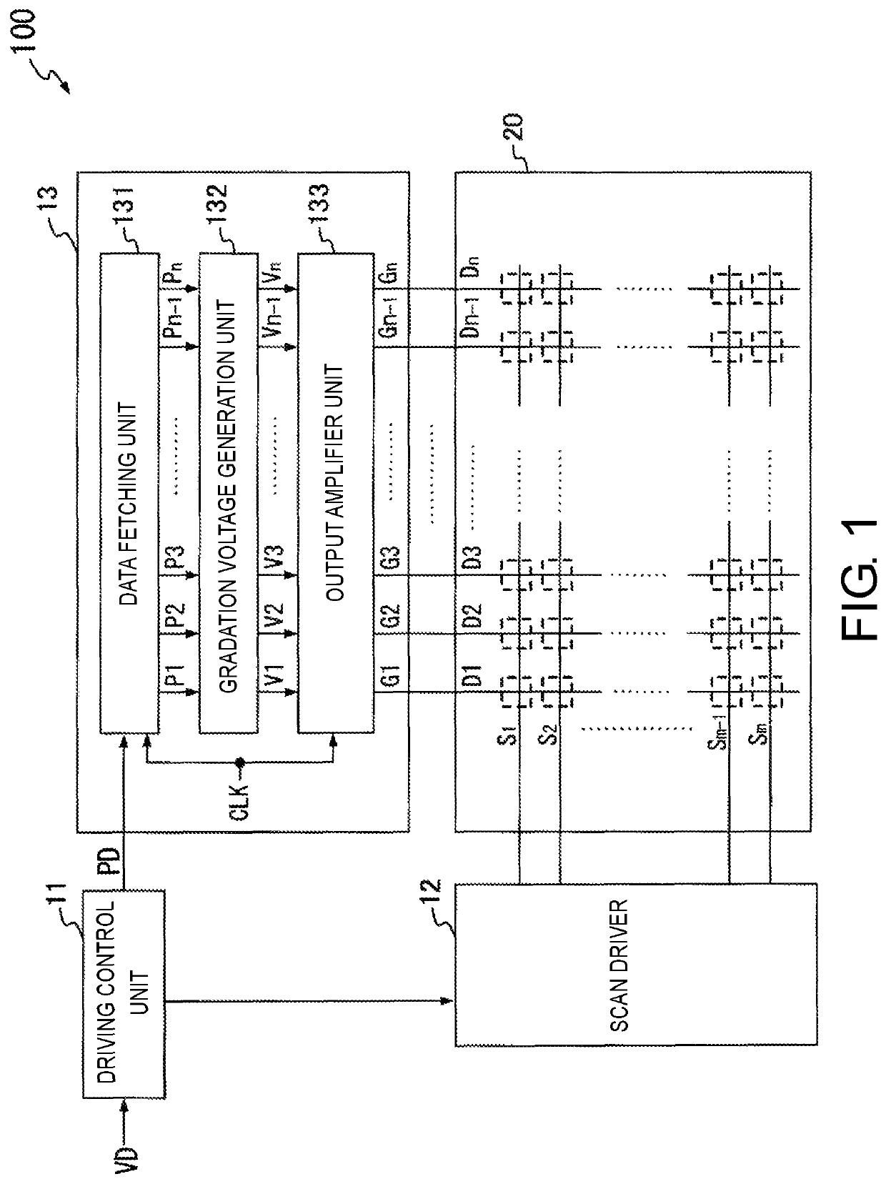
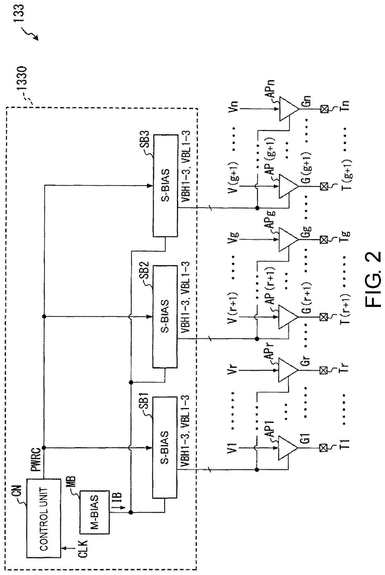
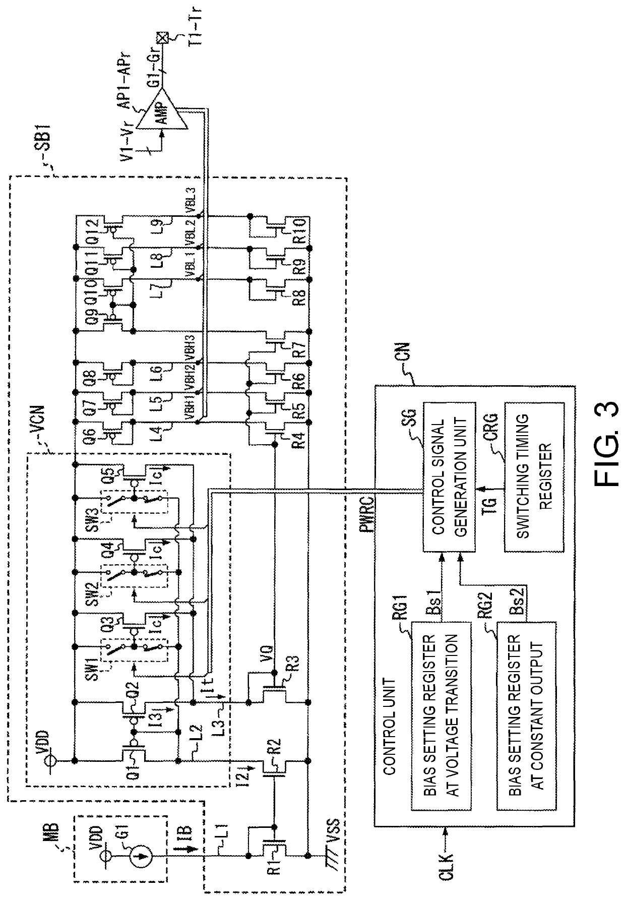
[0022]In the display driver according to the disclosure, the operation current of the amplifier that amplifies the gradation voltage supplied at the timing of the edge of the clock signal to generate the driving voltage is caused to be higher than that after a time point at which the first period has elapsed, during a period from a time point of the edge of the clock signal to the time point at which the first period has elapsed.
[0023]Accordingly, since a slew rate of the amplifier can increase during a rising or falling section of the driving voltage in which a high speed response is required, it is possible to achieve a short rising or falling time of the driving voltage. On the other hand, in a section in which the voltage value becomes constant after a time point at which the first period has elapsed, the operation current of the amplifier can be decreased, and therefore, it is possible to achieve low power consumption.
[0024]Therefore, it is possible to reliably drive the display device with low power consumption and at high speed in a small-scale configuration, as compared with a device which detects the transition period of the driving voltage by providing an amplifier that amplifies the gradation voltage and a dummy amplifier having the same characteristics as the amplifier and operating the dummy amplifier.

Problems solved by technology

Incidentally, an output amplifier is configured of, for example, an operational amplifier and a high slew rate can be obtained by increasing a current flowing in a differential stage of the operational amplifier, but a problem that power consumption increases correspondingly arises.
However, when the above technique has been adopted, the dummy amplifier must be provided in the display driver, and therefore, a size of the driver increases correspondingly.
Further, since this dummy amplifier itself consumes the same power as the output amplifier, low power consumption is hindered.
In addition, when an error occurs between a transition period of a voltage output from the dummy amplifier and a transition period of a voltage output from the output amplifier due to manufacturing variation, switching of the slew rate as described above may not be able to be performed at a correct time point.
Accordingly, it is difficult to reliably reduce the amount of power consumption and drive the display device at high speed.

Method used


Image

  • Display driver and semiconductor device comprising display driver
  • Display driver and semiconductor device comprising display driver
  • Display driver and semiconductor device comprising display driver

Examples


Embodiment Construction

[0021]According to an aspect of the disclosure, there is provided a display driver and a semiconductor device capable of driving a display device with low power consumption and at high speed while suppressing an increase in a scale of a device.

[0022]In the display driver according to the disclosure, the operation current of the amplifier that amplifies the gradation voltage supplied at the timing of the edge of the clock signal to generate the driving voltage is caused to be higher than that after a time point at which the first period has elapsed, during a period from a time point of the edge of the clock signal to the time point at which the first period has elapsed.

[0023]Accordingly, since a slew rate of the amplifier can increase during a rising or falling section of the driving voltage in which a high speed response is required, it is possible to achieve a short rising or falling time of the driving voltage. On the other hand, in a section in which the voltage value becomes con...


PUM

PropertyMeasurementUnit
luminanceaaaaaaaaaa
voltagesaaaaaaaaaa
driving voltagesaaaaaaaaaa

Abstract

A display driver includes a data fetching unit that fetches first to Nth pixel data pieces corresponding to luminance levels of respective pixels and outputs the same at a timing of an edge of a clock signal, first to Nth amplifiers that amplify first to Nth gradation voltages corresponding to the first to Nth pixel data piece to obtain first to Nth driving voltages, and a bias voltage generation unit that generates and supplies bias voltages for setting current values of operation currents to the respective amplifiers. The bias voltage generation unit stores a first value and a second value of the bias voltage used for setting the current value to a higher value and a lower value, and generates a bias voltage having the first value during a period from the timing of the edge of the clock signal, and switches the voltage value to the second value thereafter.

Description

CROSS-REFERENCE TO RELATED APPLICATION[0001]This application claims the benefit of Japan Application No. 2017-223602, filed on Nov. 21, 2017. The entirety of the above-mentioned patent application is hereby incorporated by reference herein and made a part of this specification.BACKGROUNDTechnical Field[0002]The disclosure relates to a display driver that drives a display device according to a video signal, and a semiconductor device including the display driver.Related Art[0003]A display driver that drives a liquid crystal display panel or an organic electroluminescence (EL) panel, for example, as a display device includes a plurality of output amplifiers that amplify a gradation voltage corresponding to a luminance level represented by a video signal and supply the amplified gradation voltage to source lines of the display device.[0004]In addition, with the recent increase in a screen size and higher definition of display devices, for the output amplifiers, there is a demand for sh...

Claims


Application Information

Patent Timeline
Patent Type & Authority Patents(United States)
IPC IPC(8): G09G3/3258G09G3/36G02F1/133G06F1/04
CPCG06F1/04G02F1/13306G09G3/3258G09G3/3688G09G2310/08G09G2310/0289G09G2310/0291G09G2310/0264G09G2330/021
Inventor AIZAWA, HIROKI
Owner LAPIS SEMICON CO LTD
Learn More