Stepper motor driver for mechanical engineering

a stepper motor and mechanical engineering technology, applied in the field of machines, can solve the problems of reducing the efficiency of replacing the driver, consuming a lot of working time, and increasing labor intensity, and achieve the effect of reducing labor intensity, facilitating user placement, and reducing labor intensity

Active Publication Date: 2020-11-03
DONGGUAN UNIV OF TECH
View PDF13 Cites 1 Cited by
  • Summary
  • Abstract
  • Description
  • Claims
  • Application Information

AI Technical Summary

Benefits of technology

[0005]Therefore, it is a primary objective of the present invention to provide a stepper motor driver for mechanical engineering to overcome the drawbacks of the prior art, since most drivers are installed and fixed by screws, and when a driver is damaged and needs a replacement, the driver is removed manually, and thus resulting in an increased labor intensity, consuming much working time, and lowering the efficiency of replacing the driver.
[0012]The stepper motor driver for mechanical engineering in accordance with the present invention has the following advantages: (1) The stepper motor driver for mechanical engineering comes with the first fixed plate, first spring, carrier board, third fixed plate, telescopic device and clamping plate, so that when the driver is placed on the carrier board and the carrier board is moved downwardly, the two first fixed plates are moved away from each other to shorten the two first springs. The first handle may be moved by a user's hand to move the clamping plate, so as to facilitate the user to place the driver. After the first handle is released, the telescopic device is stretched to allow the clamping plate to clamp the driver conveniently and fix the driver tightly. The driver can be removed and replaced more conveniently and quickly to achieve the effects of reducing the labor intensity, saving the working time, and improving the efficiency of replacing the driver. (2) The stepper motor driver for mechanical engineering comes with the second sliding rod and sliding block, and the second sliding rod is provided for fixing the carrier board and ascending or descending the carrier board more stably, and the sliding block is provided for supporting the clamping plate and moving the clamping plate more stably. (3) The stepper motor driver for mechanical engineering comes with the first spring and second spring, so that when the two first fixed plates are away from each other, the two first springs are shortened, and an impact force will be produced to provide a buffering effect when the driver is placed on the carrier board. When the clamping plate is moved to the right side, the second spring is shortened, and when the first handle is released, the second spring is stretched to move the clamping plate to the left side in order to clamp the driver by the clamping plate more conveniently. In addition, the present invention has the features of compact structure, reasonable design, and high practicality.

Problems solved by technology

Therefore, it is a primary objective of the present invention to provide a stepper motor driver for mechanical engineering to overcome the drawbacks of the prior art, since most drivers are installed and fixed by screws, and when a driver is damaged and needs a replacement, the driver is removed manually, and thus resulting in an increased labor intensity, consuming much working time, and lowering the efficiency of replacing the driver.

Method used


Image

  • Stepper motor driver for mechanical engineering
  • Stepper motor driver for mechanical engineering
  • Stepper motor driver for mechanical engineering

Examples


Embodiment Construction

[0017]The technical contents of the present invention will become apparent with the detailed description of preferred embodiments accompanied with the illustration of related drawings as follows. It is intended that the embodiments and figures disclosed herein are to be considered illustrative rather than restrictive.

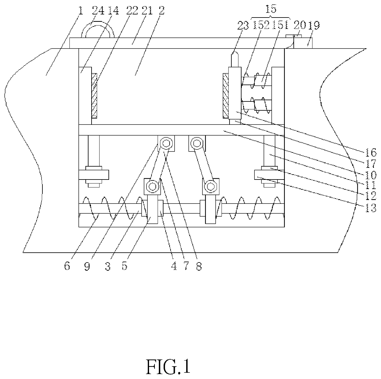
[0018]With reference to FIGS. 1 to 3 for a stepper motor driver for mechanical engineering of the present invention, the stepper motor driver for mechanical engineering comprises a bottom plate 1 with a placing slot 2 formed on the upper surface of the bottom plate 1 and provided for installing the driver more conveniently, and both sides of the inner wall of the placing slot 2 are fixedly coupled by a first sliding rod 3, and two first sliding sleeves 4 are sheathed on a surface of the first sliding rod 3, and the first sliding rod 3 and the first sliding sleeve 4 are provided for fixing the first spring 6 securely. In the meantime, two first fixed plates 5 can be set ...


PUM


Abstract

A stepper motor driver for mechanical engineering mechanical engineering includes a bottom plate, and a placing slot formed on the upper surface of the bottom plate. Both sides of the inner wall of the placing slot inner wall are fixed by a first sliding rod; two first sliding sleeves are sheathed on a surface of the first sliding rod; two first sliding sleeves are engaged with opposite sides of the two first fixed plates respectively; two first springs are sheathed on the first sliding rod, and both ends of two first springs are fixed to the sides of the two first fixed plates away from each other and both sides of the inner wall of the placing slot respectively. The driver can be removed and replaced conveniently and quickly to achieve the effects of reducing the labor intensity, saving the working time, and improving the efficiency of replacing the driver, with the design of the first fixed plate, first spring, carrier board, third fixed plate, telescopic device and clamping plate.

Description

FIELD OF THE INVENTION[0001]The present invention relates to the field of machinery, and more particularly to a stepper motor driver for mechanical engineering and the stepper motor driver has a convenient-to-install feature.BACKGROUND OF THE INVENTION[0002]Stepper motor driver is a mechanism generally used for converting an electric pulse into an angular displacement. When a stepper driver receives a pulse signal, the stepper driver drives a stepper motor to rotate to a fixed angle in a set direction, and the stepper motor is rotated step by step to the fixed angle. The number of pulses may be controlled to control the angular displacement in order to achieve the purpose of accurate positioning. In the meantime, the frequency of the pulse may be control to control the rotational speed and acceleration of the motor in order to achieve the purposes of speed adjustment and positioning.[0003]The stepper motor plays an indispensable role as a drive unit in mechanical engineering. At pre...

Claims


Application Information

Patent Timeline
Patent Type & Authority Patents(United States)
IPC IPC(8): H02P8/14H02K41/03F16B2/06H02P8/00H02K37/00H02K16/00
CPCH02P8/14F16B2/06H02K16/00H02P8/00F16B2/12
Inventor SUN, ZHENZHONG
Owner DONGGUAN UNIV OF TECH
Why Eureka
Try Eureka