
Coaxial electromagnetic apparatus

a coaxial electromagnetic and apparatus technology, applied in the field of electromagnetism, can solve the problems of reducing the performance reducing the electrical power of power-driven machines, and reducing the electrical power consumption of power generation machines, so as to reduce electrical power consumption, reduce power consumption, and improve the rotational speed of magnetic disks.

Active Publication Date: 2020-10-13
YUZEN SUSTAINABLE ENERGY PTE LTD +1
View PDF9 Cites 8 Cited by
  • Summary
  • Abstract
  • Description
  • Claims
  • Application Information

AI Technical Summary

Benefits of technology

[0008]Thus, a primary objective of the present invention is to provide a coaxial electromagnetic apparatus, which, through lowering an internal voltage when a power-driven module is not supplied with electrical power and also eliminating magnetic drag, generates completely magnetic assistance force to lower down input electrical power for driving and reduce loss of electrical power and also increase rotational speed of operation to thereby effectively increase power output.
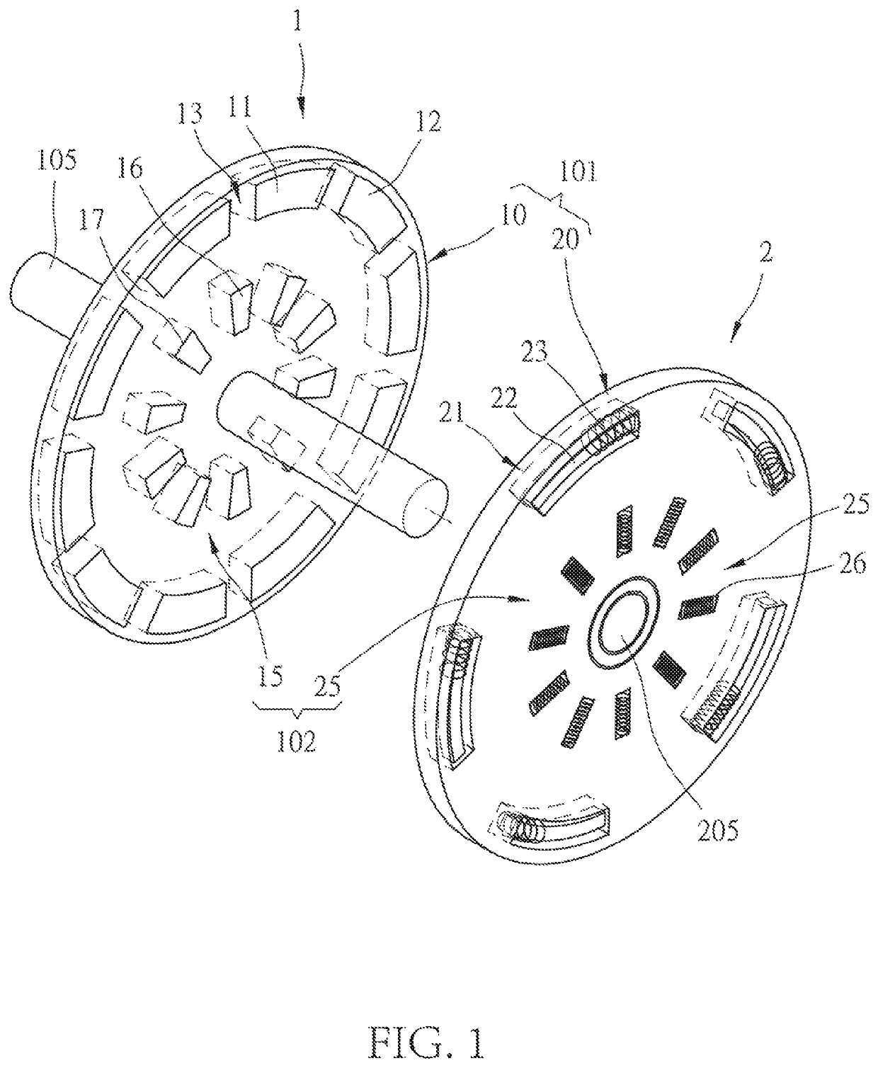
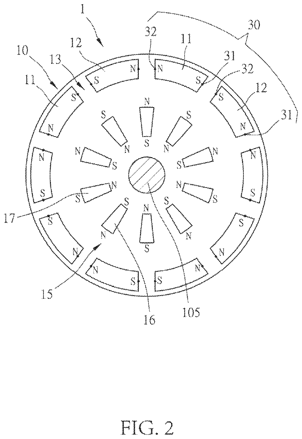
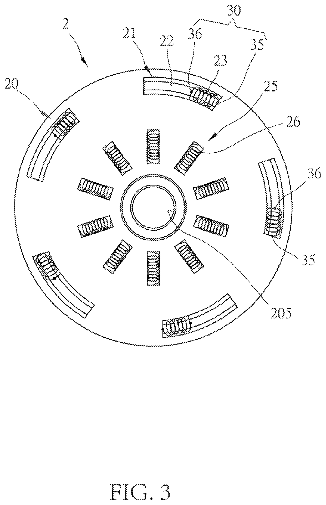
[0009]Further, another primary objective of the present invention is to provide a coaxial electromagnetic apparatus, which, through amplification of torque and good management of magnetic flow of a power-driven module, allows a rotational speed of a magnetic disk to increase, makes the power generation module generate high cutting frequency, and thus increase amount of electricity generated to meet the need of supplying power to the power-driven module so as to achieve the purpose of autonomous power generation and self-propelled motor.
[0035]As such, due to torque amplification and good management of magnetic flow of the power-driven module, the rotational speed of the magnetic disk can be increased to achieve the purpose of reduced electrical power consumption and large thrust of the power-driven module, and also to make the power generation module generate high frequency of cutting to increase the amount of electricity generated to meet the need for power supplying of the power-driven module so as to achieve autonomous power generation and self-propelled motor.

Problems solved by technology

However, in an operation of the power-driven machine, power supply is made in an intermittent fashion to allow extraction of necessary magnetic power for driving the rotor, and due to the arrangement of high magnetic flux and high cutting counts between the coils and magnetic members, in a period when the supply of electricity is temporarily cut off, the coils are still subjected to magnetism cutting by the magnetic members that are kept in motion by inertial and thus generate voltages therein.
As such, the power-driven machine would require an input of a relatively large electrical power and this causes waste of energy and would reduce the performance of the power-driven machine for outputting kinetic energy with the same input of electrical power, so that the power generation machine is no longer capable of generating a sufficient amount of electrical power for use by the power-driven machine.
In other words, the known electromagnetic apparatus that includes both functions of power generation and power driving cannot effectively avoid power generation by the power-driven machine during the time of not supplying electrical power thereto in order to lessen the internal voltage, leading to relatively large power consumption occurring in the power-driven machine, and would not meet the needs for autonomous power generation and self-propelling motor due to a relatively large magnetic drag in operation thereof and a relatively small magnetic assistance during driving.

Method used


Image

  • Coaxial electromagnetic apparatus
  • Coaxial electromagnetic apparatus
  • Coaxial electromagnetic apparatus

Examples


Embodiment Construction

[0043]The present invention is a coaxial electromagnetic apparatus, and in an embodiment of the present invention that is illustrated the accompanying drawings and the parts thereof, all the references made to front and rear, left and right, top and bottom, upper and lower, and horizontal and vertical are used only for the purposes of description and are not intended to impose limitations to the present invention, and are also not intended to limit any parts at any location or in any spatial direction. The dimensions designated in the drawings and the specification may be varied, as not departing from the scope defined by the claims of the present invention, according to the design and requirements of the embodiment of the present invention.

[0044]A structure of a coaxial electromagnetic apparatus according to the present is shown in FIG. 1, which is formed by arranging at least one magnetic disk 1 and at least one coil disk 2, which are movable relative to each other, in a spaced an...


PUM


Abstract

A coaxial electromagnetic apparatus formed of at least one magnetic disk and at least one coil disk synchronously and relatively movable and staggered at intervals. The magnetic disk and the coil disk are respectively provided with at least one power-driven module and at least one power generation module. The power-driven modules are provided at the outermost diameters of the magnetic disk and the coil disk. The power generation modules are provided at the innermost diameters of the magnetic disk and the coil disk. A rotation speed of the magnetic disk is increased due to torque amplification and good magnetic current management of the power-driven modules, thereby achieving low power consumption and large thrust of the power-driven modules. The power generation modules generate high cutting frequency to increase power generated and meet the requirement for supplying power to the power-driven modules, thereby achieving autonomous power generation and a self-propelled motor.

Description

(a) TECHNICAL FIELD OF THE INVENTION[0001]The present invention relates generally to the technical field of electromagnetism, and more particularly to a coaxial electromagnetic apparatus that is capable of simultaneously producing kinetic output and power generation in order to achieve the purposes of autonomous power generation and self-propelled motor and also to increase output power through completely magnetic assistance force, torque amplification and management of magnetic flow of a power-driven module and also to increase the amount of power generation of a power generation module.(b) DESCRIPTION OF THE PRIOR ART[0002]A regular power-driven machine adopts electromagnetism to generate high speed rotation and is made up of a stator and a rotor that are rotatable relative to each other. Taking an annular power-driven machine as an example, the stator is provided with a plurality of coils on an inner circumference thereof, and the rotor is provided with a plurality of magnetic me...

Claims


Application Information

Patent Timeline
Patent Type & Authority Patents(United States)
IPC IPC(8): H02K53/00H02K35/06
CPCH02K53/00H02K35/06
Inventor HSU, YUNG-SHUNHSU, MING-CHUNHSU, WEN-YU
Owner YUZEN SUSTAINABLE ENERGY PTE LTD
Learn More