
5G MIMO antenna structure

a technology of antenna structure and antenna, applied in the field of wireless communication, can solve the problems of increasing complexity and design difficulty of antennas, reducing the isolation between antennas, and limited space of handheld devices such as mobile phones, and achieves the effect of reducing isolation, small size and simple structur

Active Publication Date: 2020-10-13
SHENZHEN SUNWAY COMM
View PDF31 Cites 0 Cited by
  • Summary
  • Abstract
  • Description
  • Claims
  • Application Information

AI Technical Summary

Benefits of technology

The invention provides a 5G MIMO antenna structure that is simple, small, and effective in reducing isolation. It has a enclosed structure with self-isolation and a reduced size compared to traditional antennas. The use of second radiators increases the effective length of the current path and reduces the size of the antenna. Overall, this structure improves efficiency and reliability in wireless communication.

Problems solved by technology

However, due to the fact that the space of handheld devices such as mobile phones is limited, the primary issue to be settled for the MIMO antenna system is how to design small-sized antennas.
In addition, another issue to be settled for the MIMO antenna system is how to reduce the isolation between the antennas.
However, no matter which one of these designs is adopted, the complexity and design difficulty of the antennas will be increased, and antenna tuning in the later stage will become more difficult.

Method used


Image

  • 5G MIMO antenna structure
  • 5G MIMO antenna structure
  • 5G MIMO antenna structure

Examples


embodiment 1

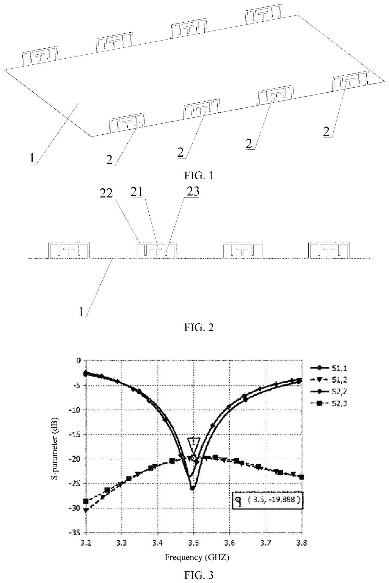
[0039]Embodiment 1: Referring to FIG. 1 and FIG. 2, the 5G MIMO antenna structure is mainly applied to communication devices such as mobile phones to fulfill 5G communications and co-exists with a 4G LTE communication system (or other antennas such as GPS antennas). As the existing 4G LTE antennas have been configured on two short edges of the mobile phones, the 5G MIMO antenna system is preferably configured on two long edges of the mobile phones.

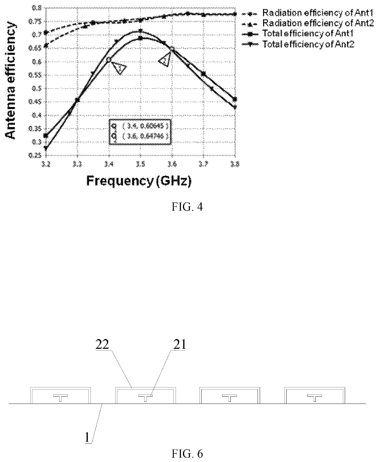
[0040]The 5G MIMO antenna structure mainly comprises a PCB 1 and more than one first antenna assembly 2 arranged on the PCB 1 at intervals. In this embodiment, the PCB 1 has a size of 150 mm*75 mm*0.8 mm, and the number of the first antenna assemblies 2 is eight, the eight first antenna assemblies 2 are symmetrically distributed on two long edges of the PCB 1, and the first antenna assemblies 2 on each edge are uniformly spaced from one another.

[0041]Each first antenna assembly 2 comprises a T-shaped feed branch 21, a first radiator 22 and...

embodiment 2

[0046]Referring to FIG. 9, this embodiment is an improvement on Embodiment 1. In this embodiment, a slot 24 is formed in the middle of the top of the first radiator 22 of each first antenna assembly 2, so that the U-structure is divided into two separated L-structures which are symmetrical with respect to the slot. The resonance frequency of the antenna can be fine adjusted by means of the slot, and the antenna is still kept bilaterally symmetrical.

embodiment 3

[0047]Referring to FIG. 10, this embodiment is an improvement on Embodiment 2. In this embodiment, the number of the first antenna assemblies 2 is four, and the 5G MIMO antenna structure further comprises two second antenna assemblies 3 and two third antenna assemblies 4, wherein the second antenna assemblies 3 and the third antenna assemblies 4 are respectively arranged at two opposite ends of the PCB 1, and the first antenna assemblies 2 are arranged in a middle of the PCB 1. As shown in FIG. 10, the second antenna assemblies 3 and the third antenna assemblies 4 are respectively arranged on the left sides and the right sides of the first antenna assemblies 2, the second antenna assemblies are identical with right halves of the first antenna assemblies 2 in structure, and the third antenna assemblies 4 are identical with left halves of the first antenna assemblies in structure. The design of configuring half the antenna structure at two ends of mobile phones is also applicable to t...


PUM


Abstract

A 5G MIMO antenna structure includes a PCB and more than one first antenna assembly arranged on the PCB at intervals. Each first antenna assembly includes a feed branch, a first radiator and two second radiators, wherein the first radiator and the two second radiators are coupled to the feed branch, the first radiator is of an inverted U-structure and has two tail ends connected to grounding points of the PCB, the feed branch is located in the first radiator and corresponds to a feed point of the PCB in position, and the two second radiators are arranged in the first radiator, connected to the first radiator, and respectively located on two sides of the feed branch. The 5G MIMO antenna structure has a good radiation effect, a good isolation effect and a smaller size, and can meet the usage requirements of a 5G system below 6 GHz.

Description

TECHNICAL FIELD[0001]The invention relates to the technical field of wireless communications, in particular to a 5G MIMO antenna structure.DESCRIPTION OF RELATED ART[0002]With the rapid development of the wireless communication technology, the fifth-generation (5G) wireless communication system will be gradually used commercially. The low-frequency band below 6 GHz and the millimeter-wave frequency band over 6 GHz are two main frequency bands adopted by the 5G wireless communication system, wherein one of the main 5G frequency bands below 6 GHz is 3.5 GHz, and one of the main 5G millimeter-wave frequency bands over 6 GHz is 28 GHz. As for the 5G system below 6 GHz, MIMO (multiple-input multiple-output) antennas will be used to increase the transmission rate of the 5G system.[0003]In order to meet the requirement for the 5G transmission rate, about eight MIMO antennas should be adopted generally. However, due to the fact that the space of handheld devices such as mobile phones is lim...

Claims


Application Information

Patent Timeline
Patent Type & Authority Patents(United States)
IPC IPC(8): H01Q7/00H01Q1/24H01Q1/22H01Q13/10H01Q21/28H01Q5/10H04B7/0413H01Q1/38
CPCH01Q13/10H01Q1/242H01Q1/2283H04B7/0413H01Q1/36H01Q1/38H01Q1/48H01Q1/50H01Q21/28H01Q9/42H01Q7/00H01Q1/243
Inventor ZHAO, ANPINGREN, ZHOUYOU
Owner SHENZHEN SUNWAY COMM
Learn More