Liquid ejecting apparatus

a technology of liquid ejecting apparatus and nozzle, which is applied in the direction of typewriters, printing, etc., can solve the problems of affecting the ejection accuracy, difficulty in cooling the driving ic by air cooling, and fluctuation of the amount, so as to achieve high quality, high eject accuracy, and high ejectivity. the effect of high quality

Active Publication Date: 2020-10-13
SEIKO EPSON CORP
View PDF13 Cites 0 Cited by
  • Summary
  • Abstract
  • Description
  • Claims
  • Application Information

AI Technical Summary

Benefits of technology

[0008]An advantage of some aspects of the invention is to provide a liquid ejecting apparatus capable of reducing heat of a driving IC.
[0021]“Industrial ink jet printer” means a printer (manufacturing apparatus) used for manufacturing an organic electro-luminescence (OEL) device, a color filter for a liquid crystal, or the like by a droplet ejecting method. The industrial ink jet printer is mainly used for manufacturing industrial products such as a liquid crystal color filter and an organic electro-luminescence device, and the like and is required to have ejection weight accuracy, enlargement for improving productivity, miniaturization for improving concentration of finished products (high resolution of ejecting unit), or the like. Further, as mass production of the same industrial product, it is assumed that the liquid is not ejected from the specific nozzle. In this configuration, since the liquid ejecting apparatus includes the nozzle which ejects the liquid by supplying the voltage waveform, the nozzle which does not eject the liquid and stirs the liquid even by supplying the voltage waveform, and the nozzle which does not eject the liquid without supplying the voltage waveform, it is possible to reduce the heat of the switching IC. Further, for example, by controlling the nozzles to which the voltage waveform is not supplied so as not to concentrate the nozzles in the nozzle row, it is also possible to reduce concentration of heating points in the switching IC. For this reason, when the liquid ejecting apparatus is used as the industrial ink jet printer, a large effect can be obtained.Application Example 7
[0023]“Textile ink jet printer” means an ink jet printer which performs printing on a fabric, or sublimation-transfers an image printed on a medium and performs printing on the fabric. The textile ink jet printer is mainly used for a purpose of producing small quantities of various types and high speed on-demand supply of products, and is used for providing a fabric in accordance with customer needs. For this reason, a highly delicate print with high quality is required and the density of the nozzles becomes higher. Therefore, since the switching IC becomes longer or the number of the nozzles becomes larger, the heat of the switching IC becomes larger. In this configuration, since the ejecting unit which does not operate so as to reduce the temperature rise of the switching IC is provided, it is also possible to reduce the heat of the switching IC. For this reason, when the liquid ejecting apparatus is used as the textile ink jet printer, a large effect can be obtained.

Problems solved by technology

However, in a structure in which the driving ICs are arranged on the piezoelectric elements in JP-A-2016-179575, since the piezoelectric element and the driving IC are arranged in a space of an almost closed state so as to prevent a malfunction due to adhesion of the liquid to the piezoelectric element and the driving IC, it is difficult to cool the driving IC by air cooling.
However, when the heating value of the driving IC exceeds heat dissipation amount which can be dissipated from the liquid, a temperature of the liquid flowing through the flow path increases according to heating of the driving IC, viscosity or the like of the liquid is changed according to the temperature rise of the liquid, and even if the piezoelectric element is driven in the same manner, there is a possibility that the ejection amount fluctuates according to a change in viscosity and ejection accuracy deteriorates.

Method used


Image

  • Liquid ejecting apparatus
  • Liquid ejecting apparatus
  • Liquid ejecting apparatus

Examples


first embodiment

1. First Embodiment

1.1 Configuration of Ink Jet Printer

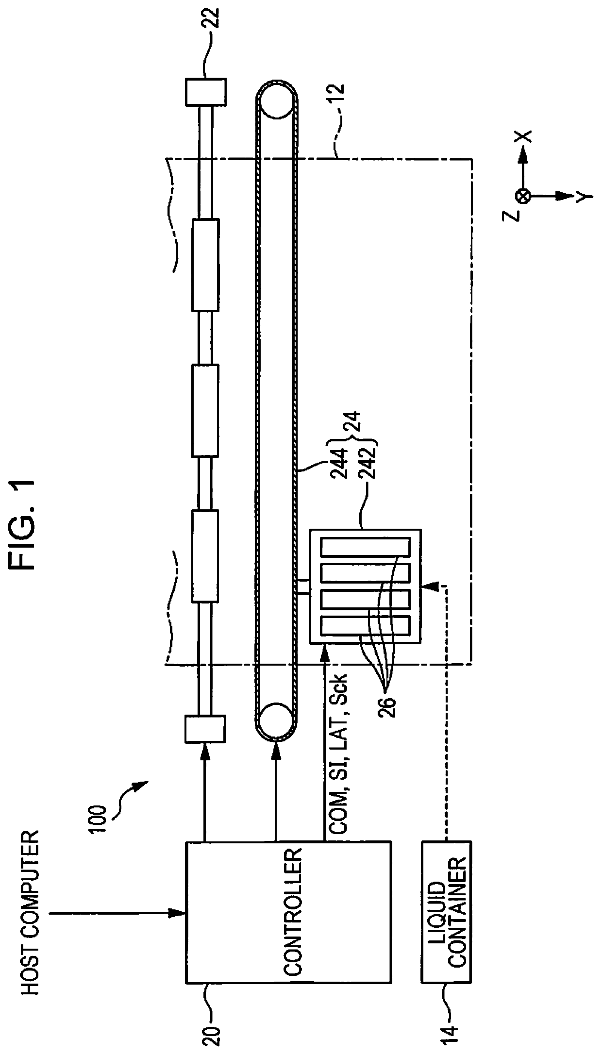
[0048]FIG. 1 is a configuration diagram illustrating an ink jet printer 100 according to the first embodiment. The ink jet printer 100 according to the first embodiment performs print by ejecting an ink which is an example of a liquid to a medium 12 and forming a dot. The medium 12 is typically printing paper, but as the medium 12, a predetermined printing target such as a resin film or a fabric can be used.

[0049]As illustrated in FIG. 1, the ink jet printer 100 includes a liquid container 14 which stores the ink. For example, as the liquid container 14, a cartridge detachable from the ink jet printer 100, an ink pack in a bag shape formed of a flexible film, an ink tank which can supplement the ink, or the like can be adopted. The liquid container 14 stores plural kinds of inks having different colors.

[0050]As illustrated in FIG. 1, the ink jet printer 100 includes a controller 20, a transport unit 22, a moving unit 24, and a p...

second embodiment

2. Second Embodiment

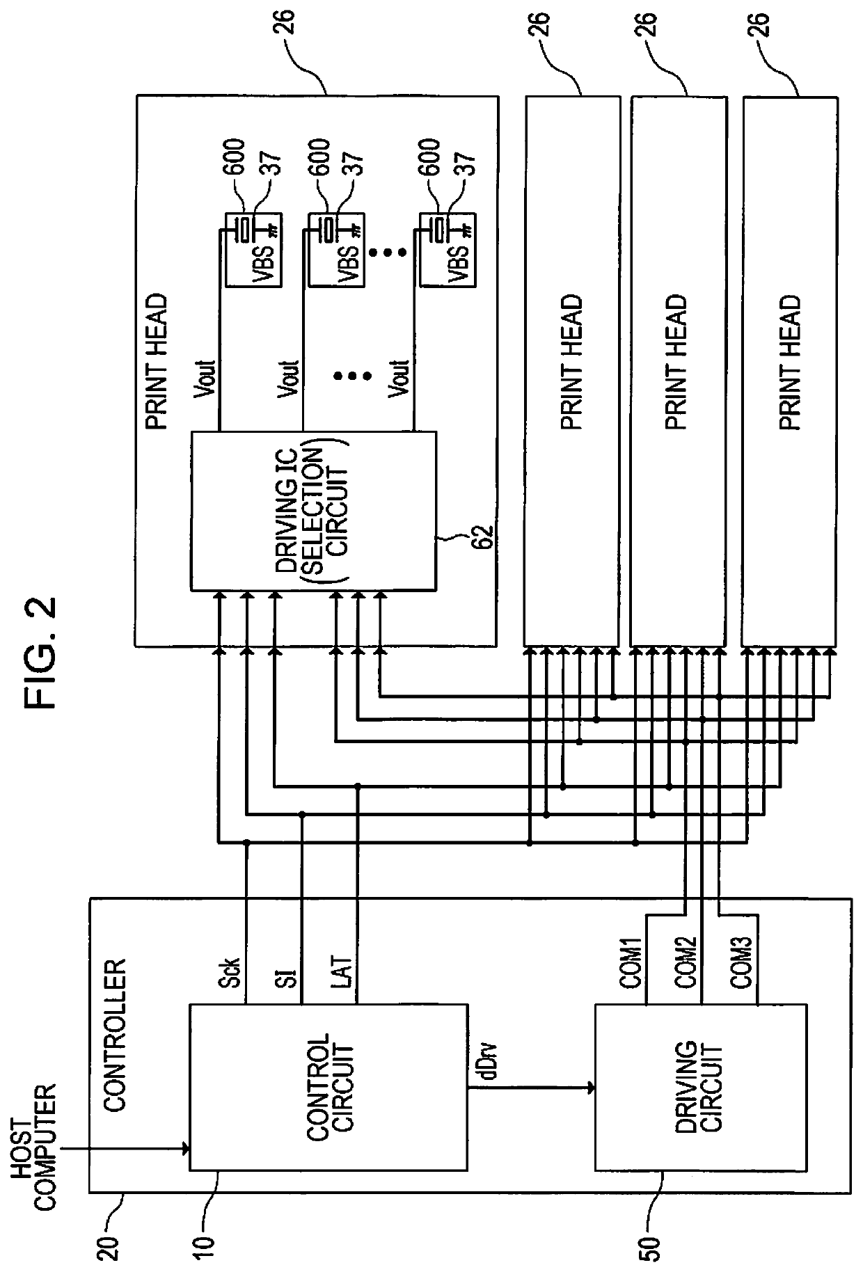
[0150]In the ink jet printer 100 according to the first embodiment, the driving circuit 50 generates the three kinds of the driving signals COM1, COM2, and COM3 and the driving IC 62 generates the driving signal Vout by switching each of the three kinds of the input driving signals COM1, COM2, and COM3 by the switches 234a, 234b, and 234c included in the switching circuit 230. In the ink jet printer 100 according to the second embodiment, the driving circuit 50 outputs one driving signal COM4 which continuously includes three kinds of the voltage waveforms Adp, Bdp, and Cdp and the switching circuit 230 generates the driving signal Vout by switching between conduct and non-conduct of the driving signal COM4 in a time division manner. Description of the same contents as in the first embodiment will be omitted. The same reference numerals are used for the same components.

[0151]FIG. 15 is a schematic block diagram illustrating the ink jet printer 100 according to th...

modification example

3. Modification Example

[0178]In the first embodiment, the driving signal COM1 which includes the voltage waveform Adp, the driving signal COM2 which includes the voltage waveform Bdp, and the driving signal COM3 which includes the voltage waveform Cdp are input to the print head 26 in parallel. In addition, in the second embodiment, the driving signal COM4 which includes the voltage waveform Adp, the voltage waveform Bdp, and the voltage waveform Cdp in a time division manner is input to the print head 26. The plurality of driving signals COM may be driving signals having a combination of these. For example, a driving signal COM-A which includes two voltage waveforms in a time division manner and a driving signal COM-B which includes two voltage waveforms in a time division manner may be input to the print head 26. When the driving signal Vout is supplied to the piezoelectric element 37, the switching circuit 230 selects and outputs the voltage waveform included in the driving signa...


PUM


Abstract

There is provided a liquid ejecting apparatus including: a first switching circuit is switched so that a first voltage waveform is supplied to a first piezoelectric element corresponding to a first nozzle which ejects the liquid, a second switching circuit is switched so that a second voltage waveform is supplied to a second piezoelectric element corresponding to a second nozzle which does not eject the liquid, and a third switching circuit is switched so that none of a plurality of voltage waveforms is supplied to a third piezoelectric element corresponding to the third nozzle which does not eject the liquid.

Description

[0001]This application claims priority to Japanese Patent Application No. 2017-163416 filed on Aug. 28, 2017. The entire disclosure of Japanese Patent Application No. 2017-163416 is hereby incorporated herein by reference.BACKGROUND1. Technical Field[0002]The present invention relates to a liquid ejecting apparatus.2. Related Art[0003]An ink jet printer, which ejects a liquid such as an ink to print an image or a document, is known to use a piezoelectric element (for example, piezo element). The piezoelectric element is provided in accordance with each of a plurality of nozzles in a print head. By driving each of the plurality of nozzles according to a driving signal, the nozzle ejects a predetermined amount of the liquid at a predetermined timing to form a dot on a medium.[0004]It is necessary to increase density of the nozzles of the print head which ejects the liquid so that the ink jet printer performs a highly delicate print with high quality of 600 dpi or more. Specifically, i...

Claims


Application Information

Patent Timeline
Patent Type & Authority Patents(United States)
IPC IPC(8): B41J2/045B41J3/407B41J2/14
CPCB41J2/04596B41J2/04593B41J2/04515B41J2/14233B41J2/04588B41J2/04541B41J2/04581B41J3/4078B41J2002/14241B41J2002/14419B41J2/045B41J2/14201
Inventor CHIKAMOTO, MOTONORIMATSUYAMA, TORU
Owner SEIKO EPSON CORP
Why Eureka
Try Eureka