
Mechanical static and dynamic measuring device based on a compound cantilevered system

a technology of static and dynamic measuring devices and cantilevered systems, which is applied in the direction of mechanical measuring arrangements, instruments, sports equipment, etc., can solve the problems of inability to measure the b's of baseball bats, inconvenient measurement of swing-class sports equipment measuring devices, and difficulty in measurement and measurement engineering, etc., to facilitate the measurement of three static mechanical properties

Active Publication Date: 2020-10-06
TECNORAMA CO LTD
View PDF7 Cites 0 Cited by
  • Summary
  • Abstract
  • Description
  • Claims
  • Application Information

AI Technical Summary

Benefits of technology

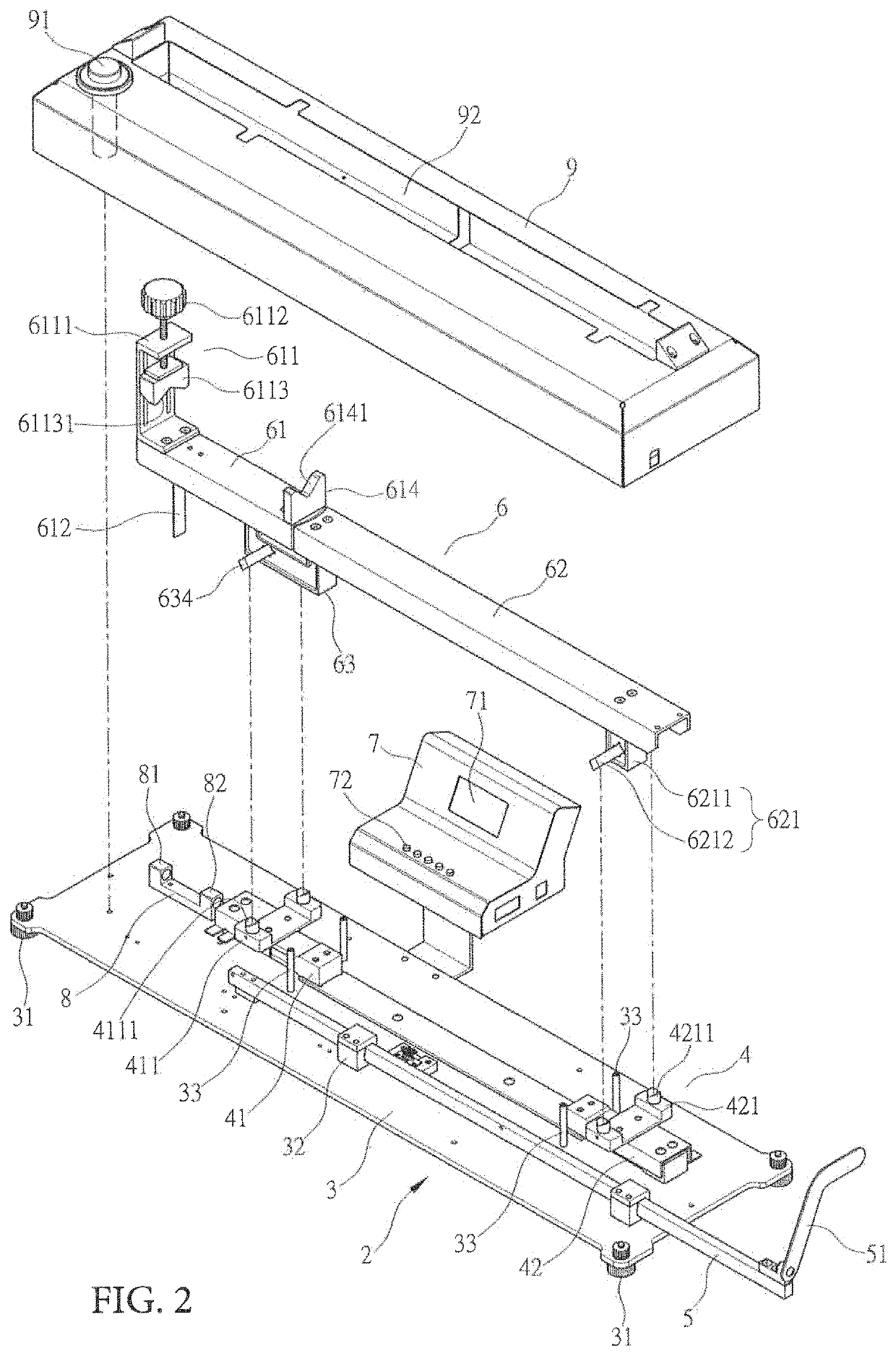
The main goal of this invention is to provide a device that can measure the size, weight, center of gravity, and moment of inertia of swing-based sports equipment simultaneously. This will solve the issue of traditional tools being unable to measure these things, making it more convenient for both riders and designers.

Problems solved by technology

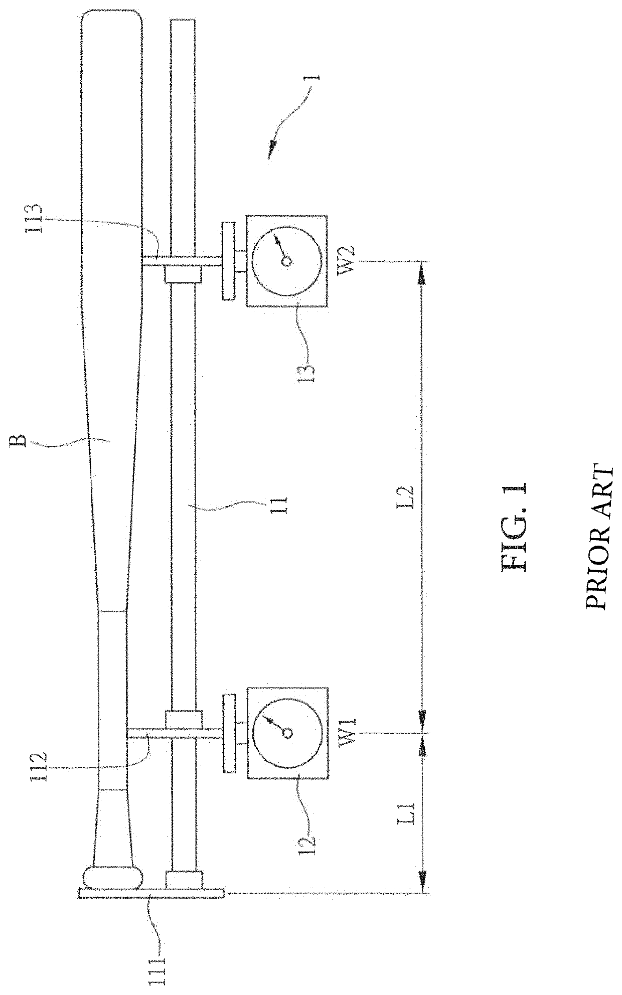
The resulting swing-class sports equipment measuring device 1 is very inconvenient in the measurement.
Moreover, the conventional swing-class sports equipment apparatus can only measure the length, weight and center of mass (center of gravity) of the baseball B. It cannot measure the baseball bat B's dynamic mechanical property such as the moment of inertia.
Thus, the conventional tools cause difficulties in measurement and the measurement engineering.
Therefore, how to provide an integrated measuring device to enhance the convenience of swing-level sports equipment measurement has become a sports equipment manufacturers' problem waiting to be solved.

Method used


Image

  • Mechanical static and dynamic measuring device based on a compound cantilevered system
  • Mechanical static and dynamic measuring device based on a compound cantilevered system
  • Mechanical static and dynamic measuring device based on a compound cantilevered system

Examples


Embodiment Construction

[0027]To help reviewing authority gain a better understanding of the structure and the effectiveness of the invention, we provide the schematic description as follows:

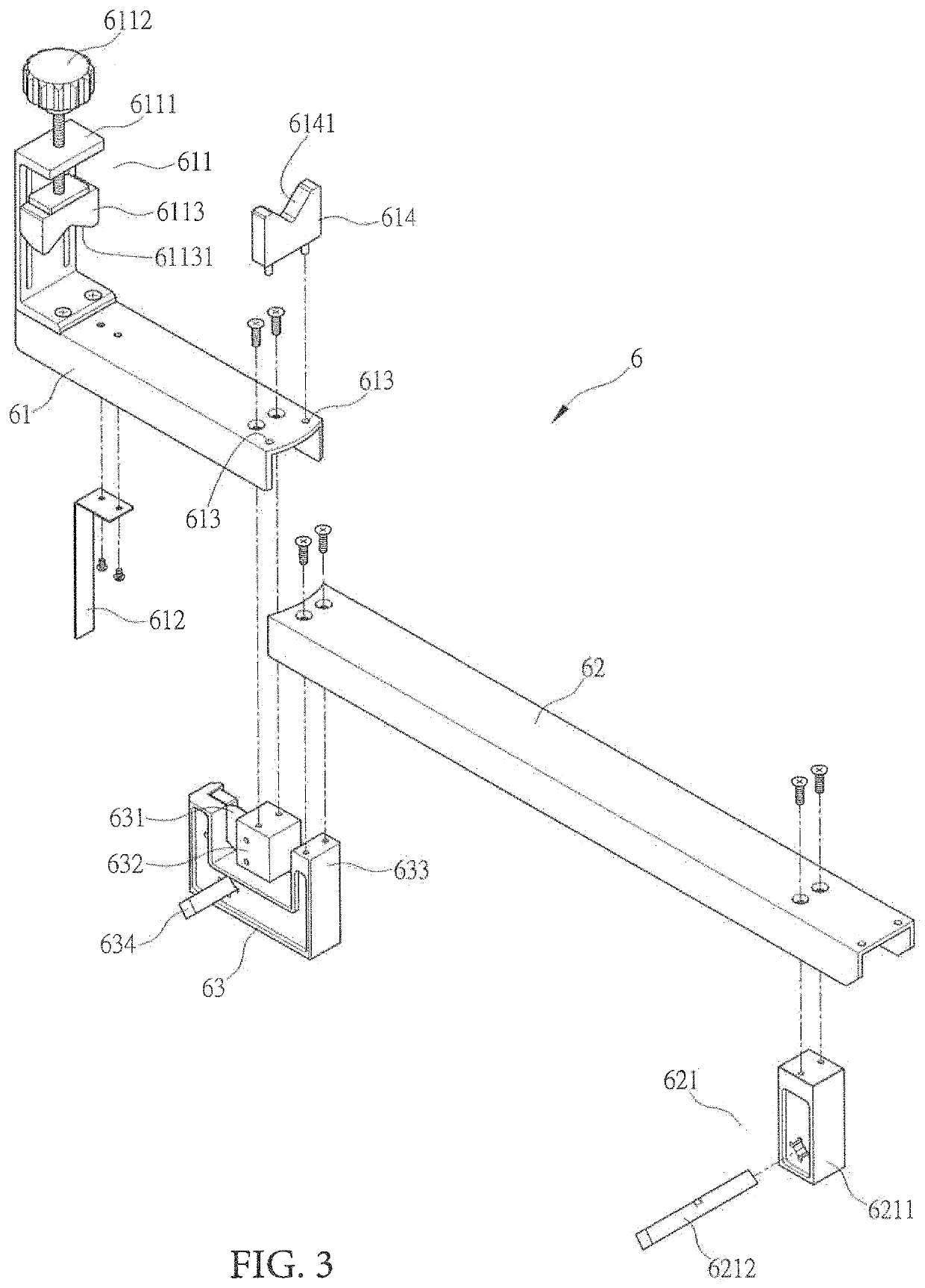
[0028]First, referring to FIGS. 2, 5 and 7, the cantilevered measuring device of the present invention comprises a base station 3, a weight station unit 4 which is on the base station 3, a base station 3 and a digital meter unit 5 located next to the weight station unit 4, a mount station unit 6 which is on the weight station unit 4 which is on one side of the base station 3 and is electrically connected to the calculation station and the display unit 7, a swing sensor 8 provided on the base station 3 and electrically connecting the calculation and display unit 7, and a cover body 9 which is sit on top of the base station 3.

[0029]As shown in FIGS. 2, 5, 6 and 7, the base station 3 is a rectangular body with four adjustable support foot pads 31 located at the four corners, which is used to adjust the level of the base s...


PUM


Abstract

A measuring device includes a base station, a weight station unit and a controller. A mount station unit is connected to the weight station unit and has first and second mounting bases connected by a swing arm. The first mounting base is moveably supported on the first weight scale, and the second mounted base is moveably supported on the second weight scale. An adjustable holding part is disposed at one end of the first mounting base and a support is disposed at another end of the first mounting base adjacent the swing arm. A sports article is mountable on the first mounting base between the adjustable holding part and the support.

Description

CROSS-REFERENCE TO RELATED APPLICATIONS[0001]This patent application claims the benefit of Taiwan Patent Application Ser. No. 106118689 filed on Jun. 6, 2017, which is incorporated herein in its entirety by this reference.FIELD OF THE DISCLOSURE[0002]The present invention relates to a compound cantilevered measuring device, in particular, a method, which can be easily used, to measure static mechanical properties of length, weight, center of mass (center of gravity) as well as dynamic mechanical property of the moment of inertia. This cantilevered measuring device applies to most swing-class sports equipment, such as golf clubs, baseball bat, jacquard, tennis racket, badminton racket, ping-pong racketBACKGROUND OF THE DISCLOSURE[0003]First of all, swing-class sports equipment or propeller rods, swing-class sports equipment, for example, which has a grip and a batting part. The user must hold the grip of a bat or a racket while he / she tries to hit the ball. The swing-class sports equ...

Claims


Application Information

Patent Timeline
Patent Type & Authority Patents(United States)
IPC IPC(8): A63B60/46G01B5/00G01G19/52G01M1/12A63B60/42G01B5/02G01M1/10A63B71/06
CPCG01B5/0023G01G19/52A63B60/42G01B5/02A63B60/46G01M1/122G01M1/10A63B2220/51A63B2220/00A63B71/0622A63B2220/803A63B2220/20A63B2220/805
Inventor LATIRI, MONDHER
Owner TECNORAMA CO LTD
Learn More